Model 35 Viscometer Instruction Manual
208878 Revision N, February 2013 19
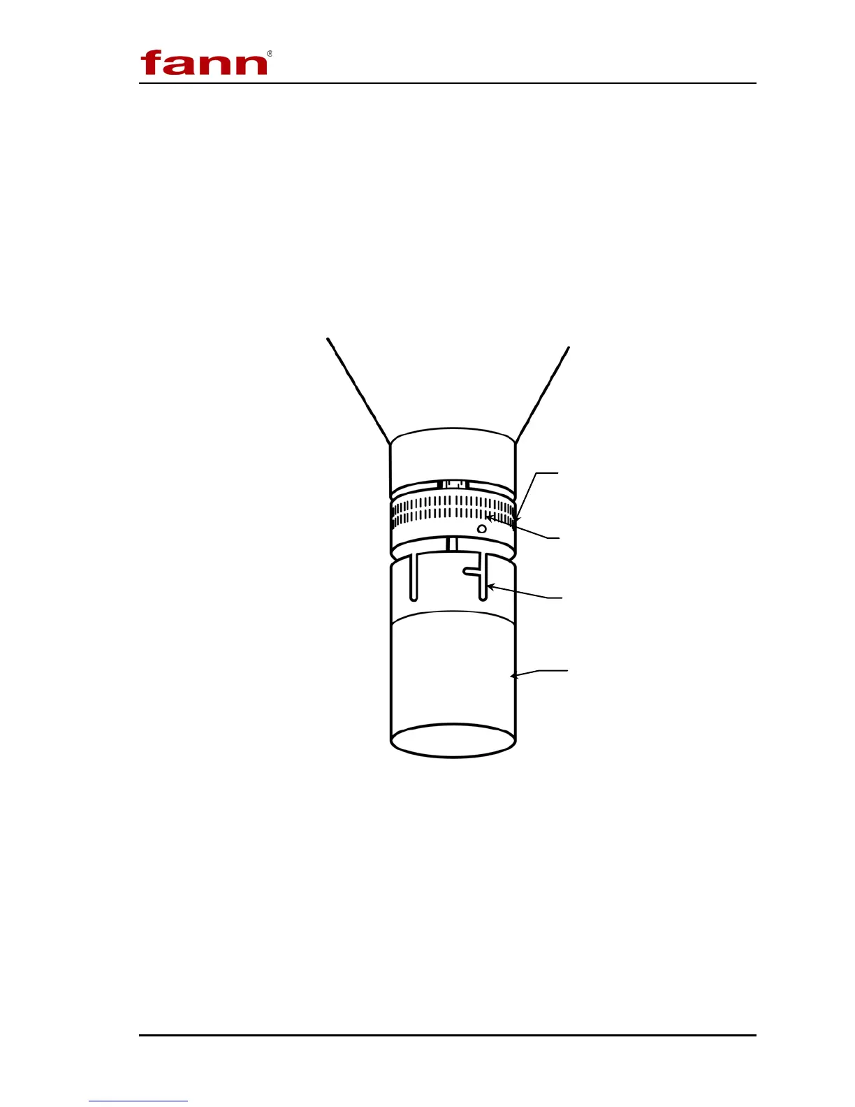
5.4.1 Rotor Removal and Replacement
Refer to Figure 5-2.
To remove the rotor from its socket, twist the rotor clockwise and gently pull it
down.
To replace the rotor, align the rotor slot and groove with the lock pin in the main
shaft socket. Then push the rotor upward and turn it counterclockwise, locking it
into position.
Figure 5-2 Rotor Removal and Installation
Slot and Groove
clockwise and pull down.
To replace rotor: Align slot and
groove with lock pin, then push
upward
and lock into place by
turning counterclockwise.