Model 35 Viscometer Instruction Manual
208878 Revision N, February 2013 30
7.3 Spring Constant Calculation
This calculation applies to the dead weight calibration method.
Equation 7-4
where
K
s
is the spring constant in dyne-cm/degree deflection
G is the load in grams
g is the gravitational constant at 981cm/sec
2
r is the radius arm at 1cm
θ is the dial reading in degrees
Example: The required setting for the F1 spring is 386 dynes/cm/degree
deflection with the R1-B1 combination. Using the 50 gram weight supplied with
the calibration kit, the spring constant is
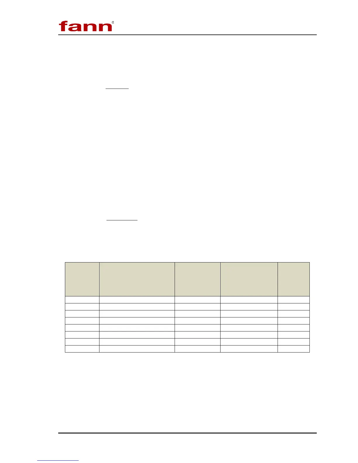
Table 7-3 Torsion Spring Specifications
Torsion
Spring
Assembly
Constant*
k
1
(dyne/cm/degree
Torsion
Spring Factor
f
Maximum Shear
Stress with B1
Bob
(dyne/cm
2
)
Color
Code
*With R1-B1 Combination