Model 35 Viscometer Instruction Manual
208878 Revision N, February 2013 29
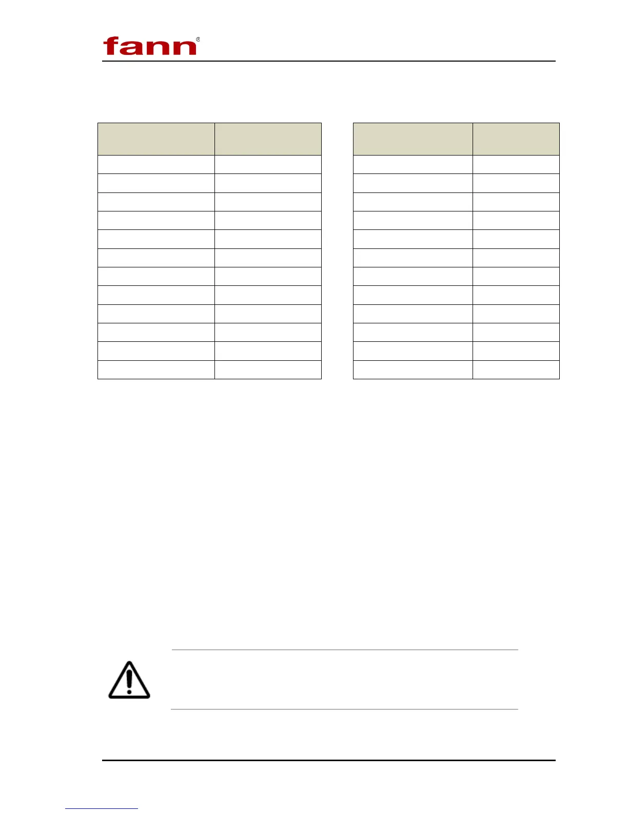
Table 7-1 Rotor-Bob Factor (C)
Table 7-2 Speed Factor (S)
Rotor-Bob
Combination
R-B Factor
(C)
Rotor
(rpm)
Speed Factor
(S)
R1-B1 1.000 0.9 333.3
R1-B2 8.915 1.8 166.6
R1-B3 25.392 3 100
R1-B4 50.787 6 50
R2-B1 0.315 30 10
R2-B2 8.229 60 5
R2-B3 24.707 90 3.33
R2-B4 49.412 100 3
R3-B1 4.517 180 1.667
R3-B2 12.431 200 1.5
R3-B3 28.909 300 1.0
R3-B4 57.815 600 0.5
7.2 Plastic Viscosity and Yield Point Calculation
Using R1-B1-F1 combination, test a sample at 600 rpm and record the dial reading.
Change the speed to 300 rpm and record the dial reading.
Determine the plastic viscosity (PV) and yield point (YP) using the following
equations. PV represents the slope of a straight line between the two dial readings.
YP represents the theoretical point at which the straight line, when projected, will
intercept the vertical axis.
PV (cP) = θ
600
– θ
300
Equation 7-2
YP (lb/100 ft
2
) = θ
300
– PV Equation 7-3
where θ is the dial reading
A spring other than F1 may be used if the dial readings are
multiplied by the proper “f” factor, but the other rotor-bob
combinations cannot be used for this two-point method.