Model 35 Viscometer Instruction Manual
208878 Revision N, February 2013 4
List of Figures
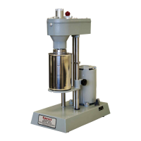
Figure 3-1 Model 35SA Viscometer ................................................................................. 9
Figure 3-2 Model 35 Viscometer Schematic .................................................................. 10
Figure 5-1 Gear Box Shift Lever .................................................................................... 16
Figure 5-2 Rotor Removal and Installation .................................................................... 19
Figure 5-3 Bob and Bob Shaft ....................................................................................... 20
Figure 5-4 Torsion Spring Removal and Replacement .................................................. 22
Figure 6-1 DW3 Calibration Fixture ............................................................................... 24
Figure 10-1 Model 35A and 35SA - Upper ..................................................................... 40
Figure 10-2 Model 35A and 35SA – Lower .................................................................... 41
List of Tables
Table 3-1 Model 35 Viscometer Specifications .............................................................. 11
Table 3-2 Model 35 Viscometer Sizes ........................................................................... 11
Table 3-3 Rotor and Bob Dimensions ............................................................................ 12
Table 3-4 Rotor-Bob Specifications ............................................................................... 12
Table 3-5 Range of Environmental Conditions .............................................................. 12
Table 5-1 Six-Speed Testing Combinations for Models 35A and 35SA ......................... 15
Table 5-2 Twelve-Speed Testing Combinations- Models 35A/SR-12 and 35SA/SR-12 . 16
Table 6-1 Dial Deflection for Calibration Weights and Torsion Spring Assemblies ......... 25
Table 7-1 Rotor-Bob Factor (C) ..................................................................................... 29
Table 7-2 Speed Factor (S) ........................................................................................... 29
Table 7-3 Torsion Spring Specifications ........................................................................ 30
Table 7-4 Constants for Viscosity Calculations .............................................................. 32
Table 7-5 Conversion Factors ....................................................................................... 32
Table 7-6 Shear Stress Measuring Range for Fann Direct Indicating Viscometer .......... 33
Table 7-7 Shear Rate Measuring Range for Fann Direct Indicating Viscometers .......... 34
Table 7-8 Viscosity Range in Centipoise for Fann Direct Indicating Viscometers .......... 35
Table 8-1 Troubleshooting Guide .................................................................................. 36
Table 9-1 Accessories ................................................................................................... 38
Table 10-1 Model 35 Series Viscometers ...................................................................... 39
Table 10-2 Model 35 Series Viscometer Parts List ........................................................ 42