EasyManua.ls Logo

Fantech 150H-EC User Manual

Fantech 150H-EC
32 pages
To Next Page IconTo Next Page
Page #1 background imageLoading...
Page #1 background image
Your ventilation system should be installed in conformance with the appropriate provincial requirements or, in the absence of
such requirements, with the current edition of the National Building Code, and / or ASHRAE’s “Good Engineering Practices”.
HERO SERIES
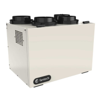
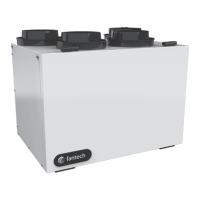
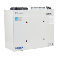
Fresh Air Appliance (HRV)
Installation and Operation Manual
Item #: 428486
Rev Date: 2020-01-23
PARTS IN THE BOX
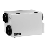
Heat Recovery Ventilator, 1 pc
Hanging Bracket, 1 pc
Drain Hose Kit, 1 pc
Operation and Installation Manual, 1 pc
Fantech reserves the right to modify, at any time and without notice, any or all of its products’ features, designs,
components and specifications to maintain their technological leadership position.
Please visit our website www.fantech.net for more detailed technical information.
United States 800.747.1762
Canada 800.565.3548
registration.fantech.app
REGISTER THIS PRODUCT TO
BE REMINDED OF SUGGESTED
PRODUCT CARE SCHEDULE
Questions and Answers:

Fantech 150H-EC Specifications

General IconGeneral
ModelFantech 150H-EC
Voltage120 V
SpeedVariable
Duct Diameter150 mm
Duct Size150 mm

Summary

Installation Types

HRV Ducting for Fully Dedicated System

Provides best fresh air distribution and lowest operation cost.

HRV/Furnace Ducting for Partially Dedicated System

Conditions fresh air before distribution throughout the house.

HRV/Furnace for Simplified Installation

Least expensive installation type, suitable for retrofitting.

Installing Outdoor Vents

Recommended Installation

Guidance on locating intake and exhaust weatherhoods away from hazards.

Installing the Vents

Steps for securing ducts and sealing connections to prevent air leakage.

Duct Installation

Connecting and Installing Ducts

Guidelines for connecting, installing, and sealing ducts to the HRV.

Air Grille Locations

Recommendations for supply and exhaust air grille placement.

Installing the Drain

Procedure for installing the condensate drain hose with a P-trap.

Mounting Options

Wall Mounting Bracket Installation

Instructions and location considerations for wall mounting the unit.

Chain Mount Installation

Steps for installing optional chain mounts and springs for vibration absorption.

Prohibited Connections

List of appliances not recommended for connection to HRV to prevent damage.

Wall Controls

Central Controls Overview

Description of individual central control options like ECO-Touch, EDF7, EDF1/EDF1R.

Auxiliary Controls Overview

Description of paired auxiliary control options like RTS2, RTS5, MDEH1.

Balancing

Entering Balancing Mode

Procedure to access the balancing menu on the ECO-Touch control.

Stage 1: Exhaust Fan Balancing

Balancing the exhaust fan at high speed using the manometer.

Stage 2: Supply Fan Balancing

Balancing the supply fan at high speed using the manometer.

Wiring Diagram - HERO 120H, 150H, 200H

Wiring Diagram - HERO 150H-EC, 250H-EC

Wiring Diagram (Cont'd)

Wiring Diagram to Furnace

Diagrams for connecting the HRV to a furnace system.

Furnace Connection to Cooling System

Wiring for connecting the HRV to a furnace cooling system.

Troubleshooting

Filter Location

Limited Warranty Information

Details on the limited warranty for the HRV components and fans.

HRV Maintenance Chart

Parts List

Notes

Related product manuals