USER MANUAL FOR FT TOWERS 26
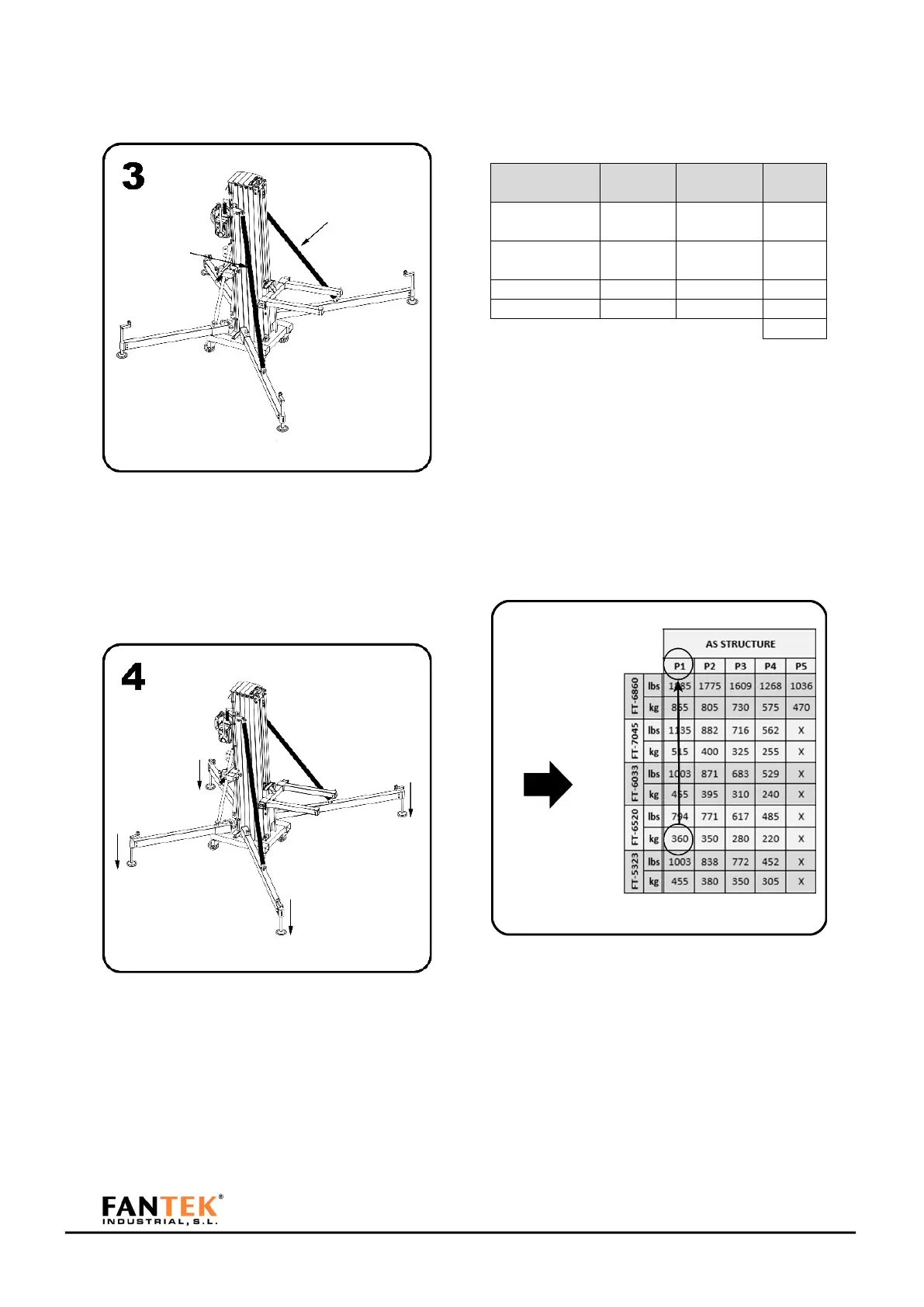
Figure 74
Place the reinforcement bars and fix them with
its pins to frontal legs.
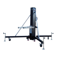
Figure 75
Place the tower in its working position and level
until the bubble level is centered. Wheels
should not take into contact with the ground
.
Calculate the load to be lifted with the tower. An
example of basic load calculation is attached.
Figure 76
In this example we have a weight of 279,50 kg.
With that load, see what position the load
should have on the tower fork. Take into account
that the truss is supported by two points of the
fork. To find out which is the largest load, take
the position farthest from the base of the fork.
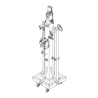
Figure 77
Choose the FT tower model. Check for the value
immediately above the load you need. With this
value, take the exact position to which the
accessory for fixing the truss must be placed.