USER MANUAL FOR FT TOWERS 32
3. When possible, place the load as close to the carriage as possible. This prolongs the life of the
tower.
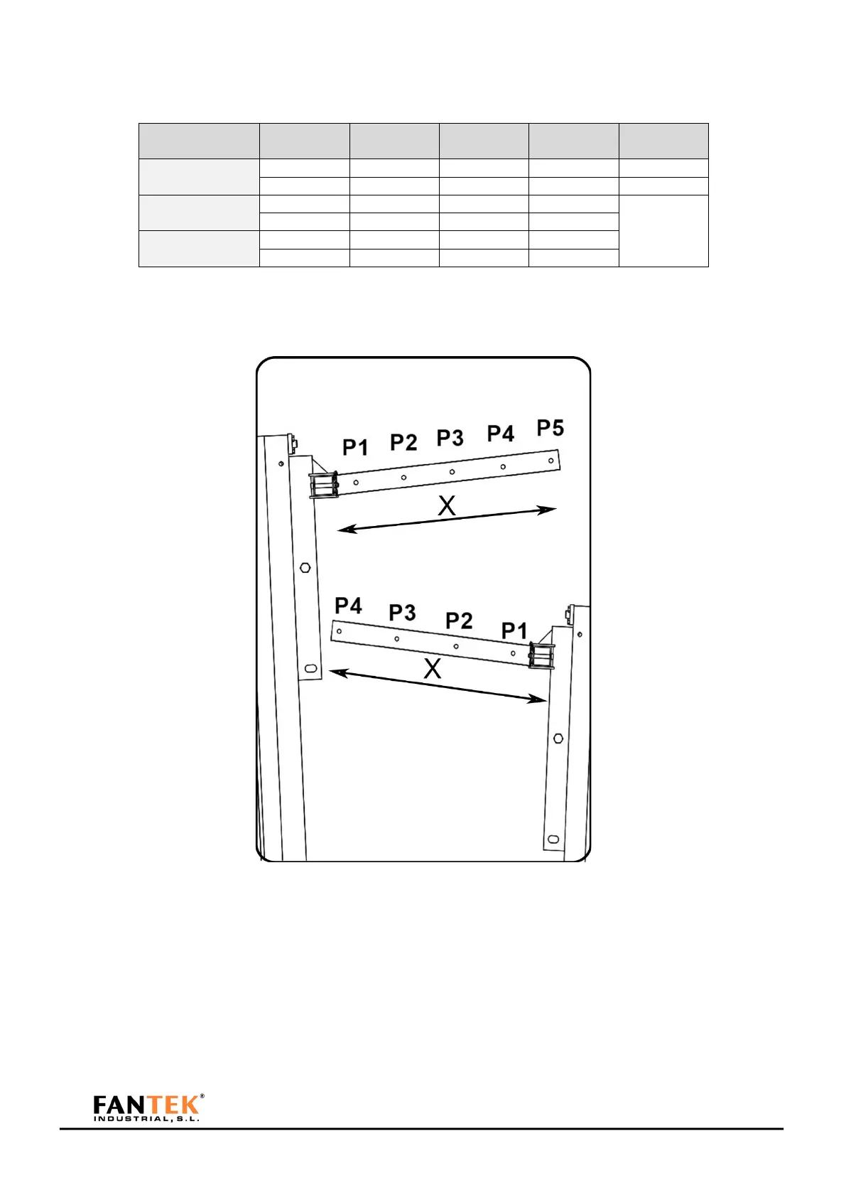
Figure 92
Detail of the position of all points of load.
Figure 93
Detail of load positions.
LOAD CHART
The maximum loads supported by each tower model, for its maximum working height can be consulted
below: