III- 18
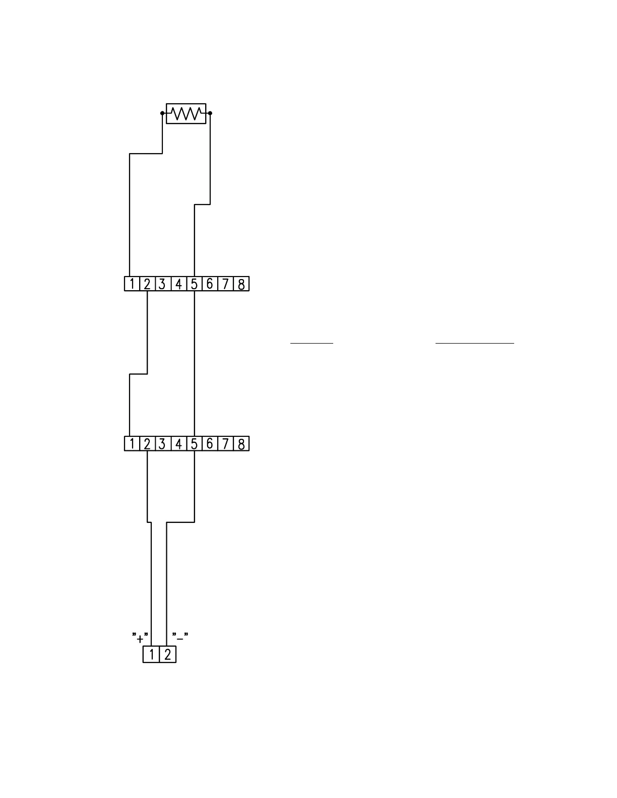
TYPICAL INITIATING DEVICE WIRING DIAGRAM
SYSTEM SENSOR TWO-WIRE (ZONE POWERED) SMOKE AND DUCT DETECTORS
Notes:
1.) This wiring diagram only shows general
information about the initiating device. For
specific wiring and installation information
read the instructions provided with each
device.
2.) For initiating circuit specifications see the
15220A Wiring Diagram (445928) or the
15240A Wiring Diagram (445929).
INITIATING
CIRCUIT
END OF LINE RESISTOR
(3.9K OHM 1/2 WATT)
FARADAY CAT. NO. SYSTEM SENSOR CAT. NO.
9176, 9177 DUCT DH400I OR
DETECTOR DH400P DUCT
DETECTOR