III- 21
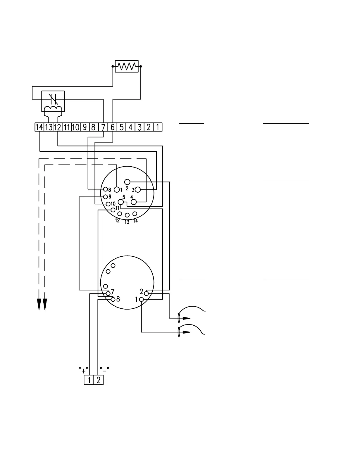
TYPICAL INITIATING DEVICE WIRING DIAGRAM
SYSTEM SENSOR FOUR-WIRE (SEPARATELY POWERED)
24V.D.C. SMOKE AND DUCT DETECTORS
Notes:
1.) This wiring diagram only shows general
information about the initiating device. For
specific wiring and installation information
read the instructions provided with each
device.
2.) For initiating circuit specifications see the
15220A Wiring Diagram (445928) or the
15240A Wiring Diagram (445929).
END OF LINE RESISTOR
(3.9K OHM 1/2 WATT)
END OF LINE RELAY
FARADAY 9423 OR
SYSTEM SENSOR A77-716-02
FARADAY CAT. NO. SYSTEM SENSOR CAT. NO.
9437 OR 9440 DUCT DH1851DC OR
DETECTOR DH2851DC DUCT
DETECTOR
FARADAY CAT. NO. SYSTEM SENSOR CAT. NO.
9362 BASE WITH B402B BASE WITH
9358, 9359 OR 1451, 2451, OR
9360 DETECTOR 2451TH DETECTOR
FARADAY CAT. NO. SYSTEM SENSOR CAT. NO.
9374, 9375 OR 1400, 2400, OR
9376 DETECTOR 2400TH DETECTOR
TO REMOTE
INDICATOR
FARADAY 9180
SYSTEM SENSOR
RA400Z
INITIATING
CIRCUIT
TO "R" TERMINAL ON THE CONTROL UNIT
TO "-" TERMINAL ON THE CONTROL UNIT