III- 22
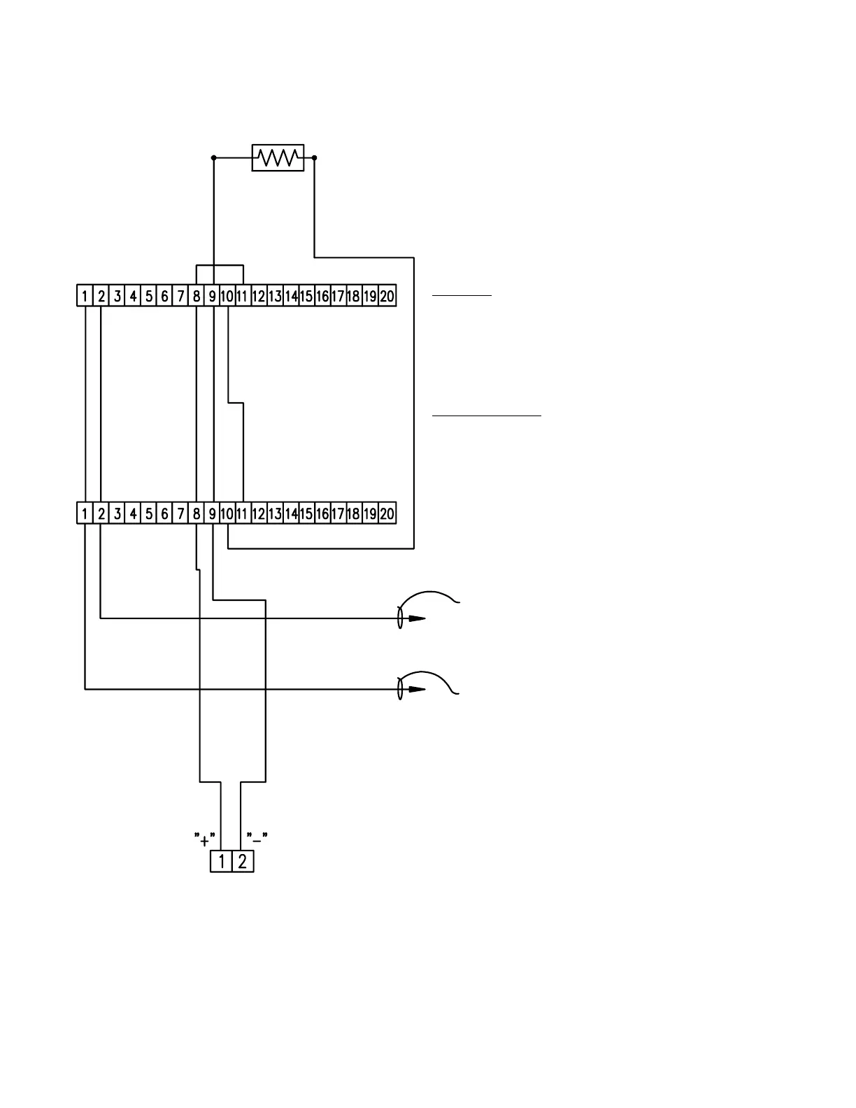
TYPICAL INITIATING DEVICE WIRING DIAGRAM
SYSTEM SENSOR FOUR-WIRE (SEPARATELY POWERED)
24V.D.C. DUCT DETECTORS
Notes:
1.) This wiring diagram only shows general
information about the initiating device. For
specific wiring and installation information
read the instructions provided with each
device.
2.) For initiating circuit specifications see the
15220A Wiring Diagram (445928) or the
15240A Wiring Diagram (445929).
END OF LINE RESISTOR
(3.9K OHM 1/2 WATT)
FARADAY CAT. NO.
9164 OR 9165
DUCT DETECTOR
SYSTEM SENSOR CAT. NO.
DH400ACDCI OR DH400ACDCP
DUCT DETECTOR
INITIATING
CIRCUIT
TO "R" TERMINAL ON THE CONTROL UNIT
TO "-" TERMINAL ON THE CONTROL UNIT