III- 39
Step 1.) Installation is to be done only by qualified personnel
who have thoroughly read and understood this
instruction sheet.
Step 2.) Disconnect all power into system, including batteries.
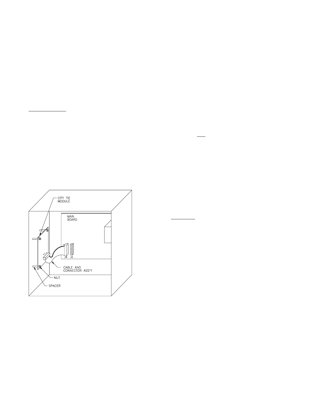
Step 3.) Install module to left side of cabinet.
A.) Place four - #10-3/8" spacers (P/N P8397-11)
over studs on the left side of the cabinet.
B.) Mount module with terminal block towards front
cover.
C.) Use four - #6-32 keps nut (P/N 18965) to secure
module in place.
D.) Plug cable and connector ass'y (P/N 444466) into
the module connector J1 and main board
connector J4 with the colored rib on the dot at
both ends.
CAUTION: Check to see that the connector are
properly seated on all of the pins.
Step 4.) Connect field wires as required.
Step 5.) Apply power to system.
Step 6.) Check for proper operation of module functions.
INSTALLATION INSTRUCTION AND WIRING FOR
CAT. NO. 15209 CITY TIE MODULE
Parts Supplied
1 15209 City Tie Module
4 P8387-11 Spacer #10- 3/8"
4 18965 Keps Nut #6-32
1 444466 Cable and Connector
Ass'y
1 444770 Instruction Sheet
The 15209 City Tie Module is an optional module for the 15220(A) or 15240(A) Fire Alarm System Control Unit.
This module provides an alarm / trouble transmitter and a form "C" system trouble contact. The module also
contains a city tie disconnect switch and a yellow trouble / off-normal switch L.E.D. The disconnect switch may
be activated during testing or servicing of the system to prevent an alarm transmission from this module (a
trouble output will be generated upon activation of the disconnect switch).
444770 - Rev. A
Module Mounting Diagram