Installation
The
units are normally supplied
set
for use with
a.c.
mains
supplies
of
24OV
nominal.
On
reguest
at
the
time
of
ordering,
units
can
be
set
for
220v
or
llOV
noninal
operation.
Units
are
set
to
ll0,
220
or
240V
input
by
neans of a simple
tap
change
on
the
trans
former,
which
is
labelled
to
indicate
the
appropri
ate
conne
ctions.
Check
that
the
unit
supplied
is
set
to the correct noninal input.
Unless
a label
on
the unit
states
220
or
l10v
it
may
be
assumed
that
the
unit
is
set
for
240V
a.c.
input.
The
mains
lead
is
wired
as
follows
:
Brown
Blue
Green/yellow
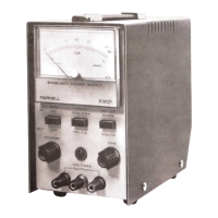
Operating instructions
OPERATING
INSTRUCTION
Depress
the
button
will
illuminate.
Observing the
correct
colour
coing
and
supply requirements connect
the
mains
lead
to
the
supply .
Mains
live
Mains
neutral
Earth
Select
the
required
VA
range
using
the
centre
push
button
marked
RAN
GE'
Depress (in)
for
0-30v and
release
(out)
for
0-15v.
Overlbad protection
INPUT
ON/OFF.
The
mains
neon
on
the
front
panel
Select
'vOLTS'
on
the
'METER'
push
button
and
adjust
the coarse
and
fine controls
until
the required output
is
shown
on
the
upper
scale
(volts)
of
the
meter.
Connections to the load are taken
from
the front panel
screw
term
inals
which
will
accept
4mm
plugs,
spade
terminals or the bared
ends
of
the
connecting
wires.
By
depressing the
'METER'
button
it
is
possible to read the
amount
of
current
being
supplied
to
the
load.
Fuses
The
current
limiting
facility
provides
automatic
protection
in
the
event
of
accidental
short
circuits
or
overloads.
This
occurs
at
approxinately
ll0%
of
the
maximum
current
on
each
range.
The
circuit
limits
the
current
that
may
be
drawn from
the
unit.
With
progressive
overload the
voltage
at
the
output
falls
while the
current
remains
On
removal
of
overload
the
output
will
reset
automatically
to
its
original
voltage.
The mains
input
and
regulated
output
circuits
are
each
protected
by
fuses
accessible
on
the
back
panel
of
the
unit.
Before removing
either
fuse ensure the
unit
is
dis connected
No
te
:
from
the
mains supp
ly
General
The
output
from
the
twO
main
secondaries
of
the
mains
transformer
MT1
are
switched
by
Sw2
a
and
sw2b
in
series
or
parallel
for
0-30
or
O-15
volt
operation
respective
ly.
This
a.c.
voltage
is
rectified
by
a
bridge
and
smoothed
by
a
reservoir
capacitor
to
provide
an
un
stabilised
d.c.
supply.
The
positive
of
the
unstabilised
supply
is
fed
to
the
collector
of
VT6
(and
vT7)
through
Rl6
(and
Rl8)
to
the
positive
output terminal. The
negative
of
the
unstabilised
supply
is
fed
through
F2
to
the
negative
output.
An
auxiliary
supply
for
Stabilisation circuit
CIRCUIT
DESCRIPTION
Current
is
taken
from
the
auxiliary
supply
across
C1
and
fed
through
R1
to
zl
which
is
the
first
zener
iode
and
provides
rough
stabili
sation.
The
voltage across
Zl
is
further
stabilised
by
~2,
D3
and
Z3
which
are
fed
by
R2.
These provide the
stabilised
voltages
for
the
amplifier,
namely
+10v
(nominal ) -0.7V
(nominal)
and
-5.8v
(nominal) ,
which
are
referred
to the positive output terminal via
the
feedback
connection.
Current
from
the
+l0V
line
is
passed
thro
ugh
R3
to
z4
which provides a
stable
reference
voltage.
The
reference
voltage
passes
current
down
the
potential
divider
formed by
R4
and
Tl
and
Pl
and
P2.
(R7
and
T2
shunt
Pl
and
P2
through
SW2c
only
in
the
O-15V mode) The
other
end
of
the
potential
divider
is
connected
via
the
negative
feedback
lead
to
the
negative
output.
The
differential
amplifier
formed
by
vTl and
vT3
senses
any
Thus, assuming
the
voltage
on
the
output
tries
to
rise,
the
base of
VTl
will
become
negative
and
VTl
will
tend
to
turn
off.
This
reduces
the
current
through
R5
and
the
base/emitter
junction
of
VT2
decreas
ing
the
current
through
VT2
collector
This
decreases
the
current
drive
into
VT5
base
through
R8,
and hence
the
current
drive
into
vT6
base.
Therefore
the
current
into
the
output
load
and
the
voltage
across
it
decreases.
Alternatively
if
the
voltage
on
the
output
tends
to
go down,
the
reverse
process
increases
the
output
current
and
therefore
the
output
voltage.
The
sum
effect
is
to
keep
the
voltage
at
a
value
fixed
by
the
value
of
Pl
and
P2
against
all
load
variations.
24
provides
a
stable
ref
erence
against
mains
supply
variations.
Overload
protection
The
current through
Rl6
gives a voltage proportional to output
cur
rent.
This
is
sensed
by
R9,
and
R10. RlO
provides
a
negative
bias
on
the
base
of
VT4
which
is
turned
off
in
normal
use.
As
the
output
current
rises
the
voltage
at
the
base
of
VT4
rises
until
it
is
positive
enough
with
respect
to
VT4
emitter,
which
is
set
at
-0.7V,
to
turn
vT4
on.
Drive
current
to
the
base
of
VT5
is
then
shunted
through
VT4
collector.
This
limits
the
maximum
current
available
at
the
output.
The
value
of
current
available
is
preset
by
T3.
On
removal
of
the
overload
VT4
is
switched
off
and
the
out
Rll
is
switched
to
5
approxinately
constant.
the
stabilising
circuit
is
obtained
from
the
other
secondary winding,
which
is
rectified
by
Dl
and
D2
and
smoothed
by
Cl.
voltage
difference
between
the
junction
of Tl
and
Pl,
and
the
posi
tive
output.
put
voltage
returns
to
its
previous
level.
 Loading...