2
Fig. 2.2
1855
_6
c--14
-3
-4_1
_6
_15
-10
-3---4
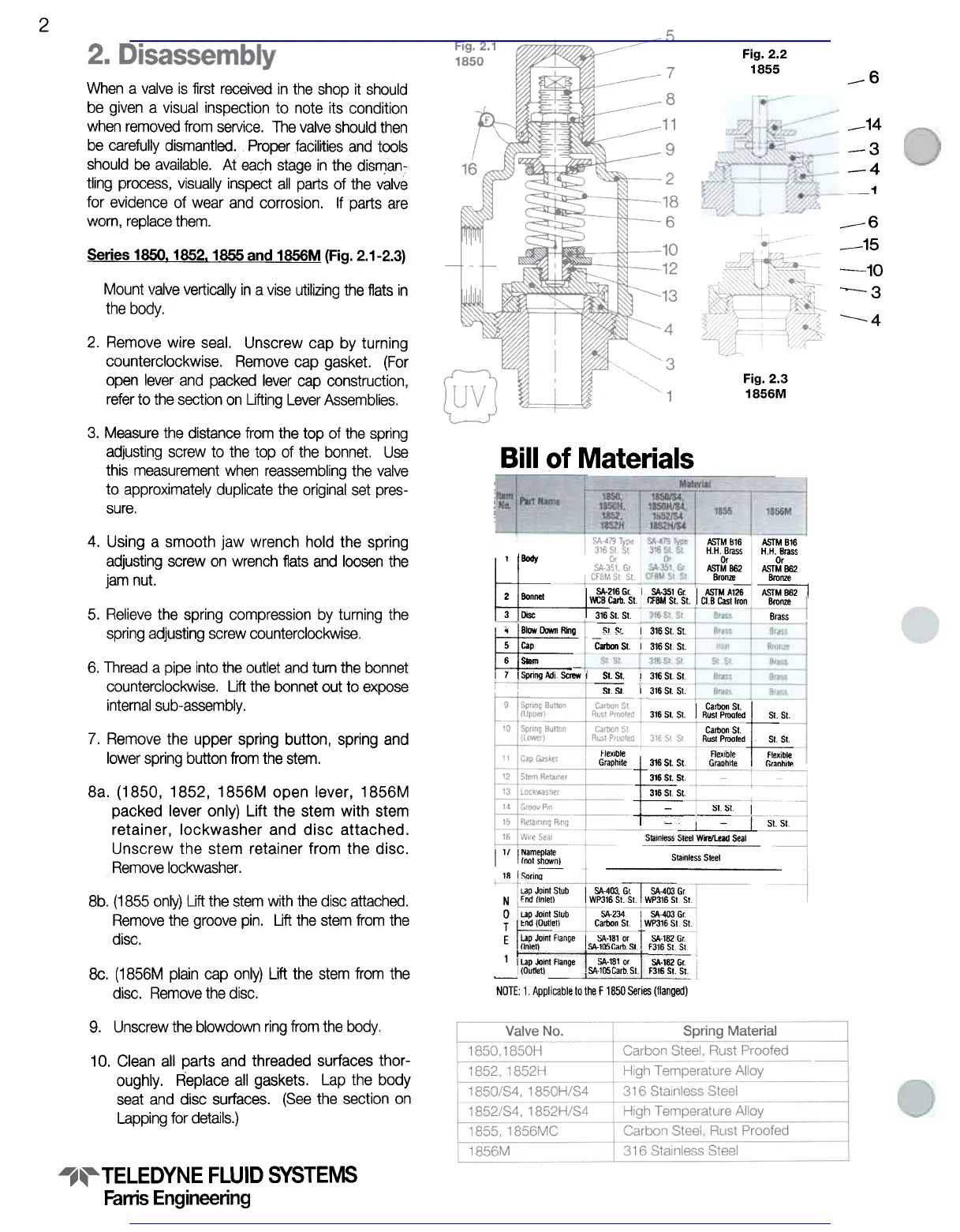
Series 1850. 1852.1855 and 1856M (Fig. 2.1-2.3)
Mount valve vertically in a vise utilizing the flats in
the body.
2. Remove wire seal. Unscrew cap by turning
counterclockwise. Remove cap gasket. (For
open lever and packed lever cap construction,
refer to the section on Lifting Lever Assemblies.
Fig. 2.3
1856M
3. Measure the distance from the top of the spring
adjusting screw to the top of the bonnet. Use
this measurement when reassembling the valve
to approximately duplicate the original set pres-
sure.
Bill of Materials
4. Using a smooth jaw wrench hold the spring
adjusting screw on wrench flats and loosen the
jam nut.
SA-4791Ype
31681 81.
Or
SA-3S1. Gr
Cf8M 51. 51.
ASTM 816
HH 8rass~
Body Or ASTM B62 Bronze
SA-216 G( I SA-351 G( ~MA126
2 Bonnet Y«:B Carb. 51 CFBM 51. 51 I CIS Cast Iron
3 Disc 316 51 51
51. 51
ASTM B16
HH. Brass
Or
ASTMB62
Bronze
ASJM 862 ,
Bronze
5. Relieve the spring compression by turning the
spring adjusting screw counterclockwise.
316 5t 51
Brass
Brass
Iron
St St
Brass
Brass
Brass
:. I 316 St St
-~~~!
316StSt
Blass
Bronze
Brass
Brass
Brass
~ BIow riI7N!, Ring
5 Cap
6s.m
! 316 51 51
6. Thread a pipe into the outlet and turn the bonnet
counterclockwise. Uft the bonnet out to expose
internal sub-assembly.
I 7 ISpringAdj Screw i ~
St. St
131651 51
~
I 31651. 51.
I Carbon 51.
f:g316 51. 51. AuSI Proofed 51. 51. Carbon 51.
Ausr PrOOled 51. 51
Flexible
GraDhile
7. Remove the upper spring button, spring and
lower spring button from the stem.
Flexible
Graphite
Flexible
Graphite
316 51. 51
31651.51
31651 51
;;;
8a. (1850, 1852, 1856M open lever, 1856M
packed lever only) Lift the stem with stem
retainer, lockwasher and disc attached.
Unscrew the stem retainer from the disc.
Remove lockwasher.
51 51
1 17 INameplate
(not shfNIn)
18 I SDrin-;;-
-~ I
I -I
Stainless 51..1 WOe/lead Seal
Stainless Sleel
Lap Joint Stub
I $A-403, G;T":SA:403 Gr.
End ilnlet) WP316 SI-St I WP316 St SI
8b. (1855 only) Lift the stem with the disc attached.
Remove the groove pin. Lift the stem from the
disc.
SA-234 I SA 403 Gr.
Carbon SI. WP316 SI. SI.
N
0 ! Lap Joint Stub
T
~nd (Outlet)
E Lap Joint flange I SA-181 or T SA-182 Gr
(Inlet) SA-105CarbSt f316 St St
1
IUPJointflange ~
~ (Outletl F316 S~
NOTE: 1 Applicable to the F 1850 Series (lianged)
SA.181 or
ISA.105CarbSt
Sc. (1856M plain cap only) Lift the stem from the
disc. Remove the disc.
9. Unscrew the blowdown ring from the body.
10. Clean all parts and threaded surfaces thor-
oughly. Replace all gaskets. Lap the body
seat and disc surfaces. (See the section on
Lapping for details.)
TELEDYNE FLUID SYSTEMS
Farris Engineering
When a valve is first received in the shop it should
be given a visual inspection to note its condition
when removed from service. The valve should then
be carefully dismantled. Proper facilities and tools
should be available. At each stage In the dismao-:
tling process, visually inspect all parts of the valve
for evidence of wear and corrosion. If parts are
worn, replace them.
Visit www.boighill.com to request a quote.
Visit www.boighill.com to request a quote.