7
WATER -Before starting the seat tightness test, the outlet
body bowl shall be filled with water, and the valve shall be
allowed to stabilize with no visible flow from the valve outlet.
The valve shall be observed for "1 minute at the test pressure.
There shall be NO VISIBLE LEAKAGE at the valve outlet.
Soft Seated Valves
Soft seated valves shall be tested at 95% of set pressure
when set above 100 psig; they shall be tested at 5 psig
below set pressure when the set pressure is less than or
equal to 100 psig.
8l8: There shall be NO LEAKAGE (ZERO BUBBLES) using
the test method outlined above.
STEAMgng WATER: There shall be NO VISIBLE LEAKAGE
at the valve outlet.
2. If any valve fails to meet leakage requirements it shall be
reworked.
3. Assemble appropriate CAP CONSTRUCTION after leak
tightness has been verified. If valve type is OPEN LEVER,
no back pressure test is required. PLAIN CAP and
PACKED LEVER valves must be back pressure tested as
outlined in the next section.
BACK PRESSURE TEST
1. This test applies to all valves designed for discharge to a
closed system (PLAIN or PACKED LEVER CAP CON-
STRUCTION) with inlet sizes larger than 1" NPS.
2. The secondary pressure zone of the valve shall be tested
with air or other suitable gas at a pressure of at least 30
psi. The valve should be pressurized at the outlet with
shop air or other means. A soap solution or other suitable
solution shall be applied to all connections which are
potential leakage paths (i.e., body/bonnet connection,
cap/bonnet connection, packed lever assembly/cap con-
nection). No leakage is acceptable.
3. If leakage is detected at any location the valve shall be
reworked.
~~ TELEDYNE FLUID SYSTEMS
FarTis Engineering
TESTING AND SETTING PROCEDURE:
1. Mount the valve on the test stand. Use air as the test
medium for air, gas and vapor or flashing service appli-
cations. Set valves for saturated steam service on satu-
rated steam. Valves for steam service set with air
should include temperature compensation. The name-
plate provides "Cold Differential Set Pressure." Set
valves for liquid service on water.
2. Hold the STEM tightly and tighten (turn clockwise) the
SPRING ADJUSTING SCREW to increase the spring
force. Make sure the stem does not rotate while load-
ing the SPRING.
3. Slowly raise the test drum pressure and observe the
opening point. The set pressure on air or steam is the
"pop point" while on water it is the first continuous flow.
4. If necessary reduce the test drum pressure and adjust
the SPRING ADJUSTING SCREW. Repeat this until the
valve opens at the required pressure, designated as
"Cold Differential Set Pressure." At the desired setting,
torque the JAM NUT to 25 FT. LBS. and assemble CAP
and GASKET for tightness testing. Check set point once
more after locking JAM NUT.
NEVER ADJUST THE SPRING SETTING WHEN THE
PRESSURE UNDER "THE VAL VE IS NEAR ITS POPPING
POINT; AS THE BODY SEA T AND DISC SEA T MIGHT
SCORE AND/OR GALL. ALWAYS LOWER THE PRES-
SURE IN THE VALVE AT LEAST 25 PERCENT BELOW
POPPING PRESSURE BEFORE MAKING ADJUST-
MENTS. THIS WILL PUT A LOADING ON THE SEA TfNG
SURFACES, THUS PREVENTING ROTATION AND DAM-
AGE. SEAT TIGHTNESS TESTING
SEAT TIGHTNESS TESTING
NOTE: The valve must be checked for seat leakage after the
set pressure has been checked. Excessive leakage could
lead to fouled or inoperable valves, serious product loss and
could be hazardous to personnel and equipment.
1. The valve can be tested for tightness on the test stand by
increasing vessel pressure to the required test pressure
and observing the valve outlet for evidence of leakage.
The following is an overview of the test procedures used.
Metal Seated Valves:
Metal seated valves shall be tested at 90% of set pressure
when the set pressure is greater than 50 psig; they shall be
tested at 5 psig below set pressure when the set pressure is
less than or equal to 50 psig.
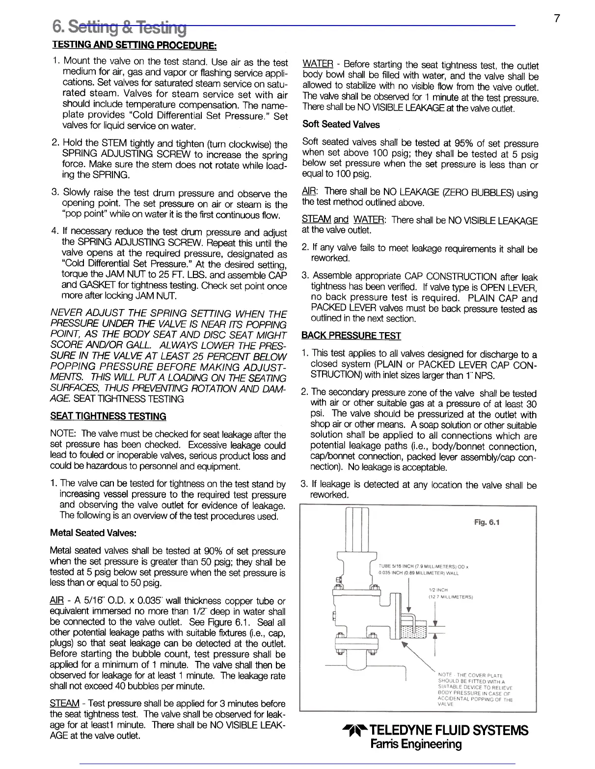
A!B -A 5/16' 0.0. x 0.035' wall thickness copper tube or
equivalent immersed no more than 1/2" deep in water shall
be connected to the valve outlet. See Figure 6.1. Seal all
other potential leakage paths with suitable fixtures (i.e., cap,
plugs) so that seat leakage can be detected at the outlet.
Before starting the bubble count, test pressure shall be
applied for a minimum of 1 minute. The valve shall then be
observed for leakage for at least 1 minute. The leakage rate
shall not exceed 40 bubbles per minute.
STEAM -Test pressure shall be applied for 3 minutes before
the seat tightness test. The valve shall be observed for leak-
age for at least1 minute. There shall be NO VISIBLE LEAK-
AGE at the valve outlet.
Visit www.boighill.com to request a quote.
Visit www.boighill.com to request a quote.
 Loading...