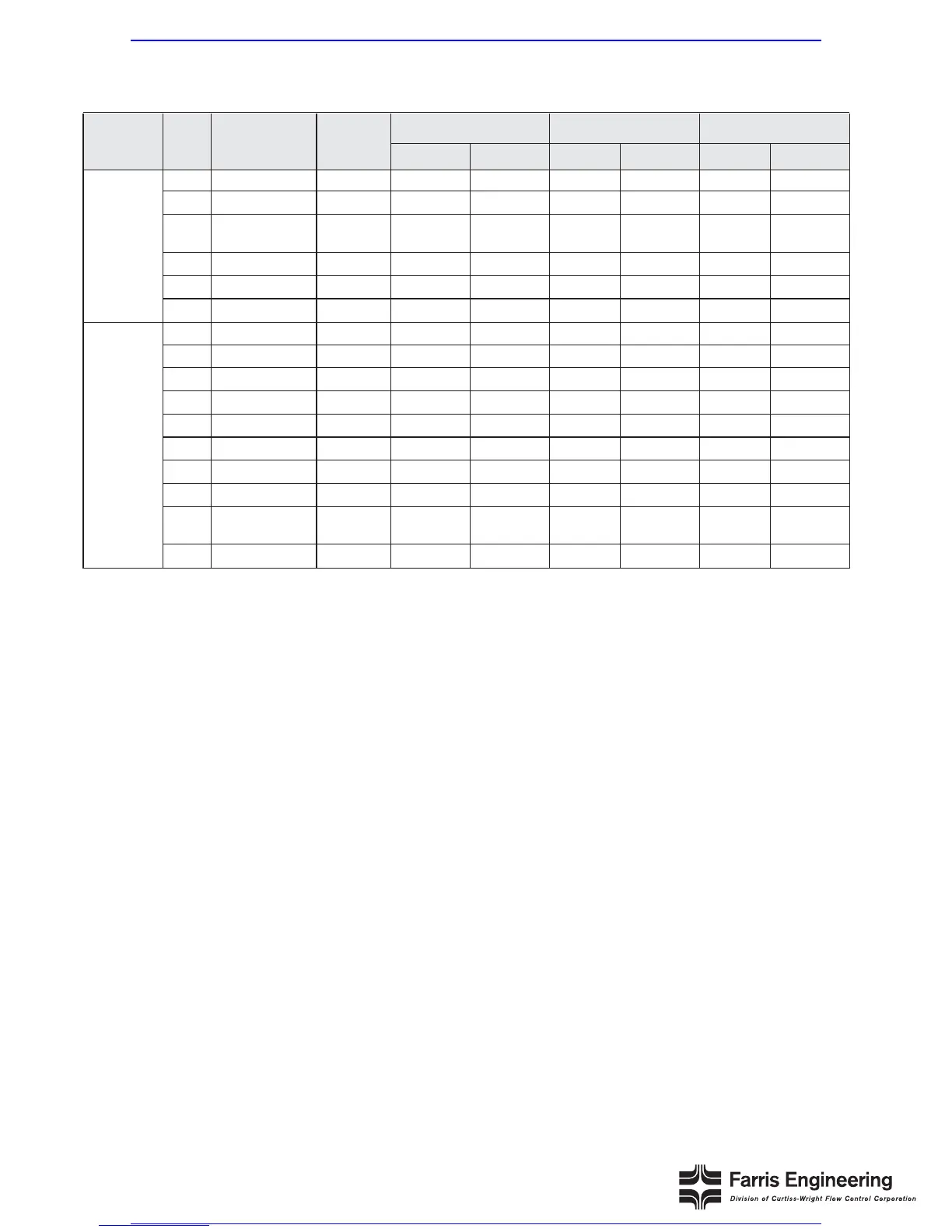
Accessories
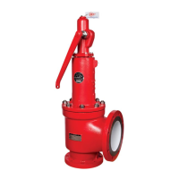
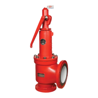
Cap Construction: M70 Open Lever, M40 Packed Lever
General Notes:
1. Any part denoted with a dash is standard material. 2. S4 trim is suitable for cryogenic service.
Cap
Construction
Item
No.
Part
Name
Standard
Materials
316 St. St.
S4
S7
Monel
M1 & M2
M4
Hastelloy C
H1 & H2
H4
M70
Open
Lever
M40
Packed
Lever
1
2
3
4
5
6
7
8
9
10
11
12
13
14
15
16
Test Lever
Cap, Open Lever
Stem Test
Washer
Stem Jam Nut
Button Head Rivet
Set Screw
Test Lever
Cap, Packed Lever
Stem Test Washer
Stem Jam Nut
Cam
Gland
Gland Nut
Packing Ring
Gland Nut Gasket
Groove Pin
Iron
Iron
St. St.
St. St.
Steel
Steel
Steel
Steel
St. St.
St. St.
St. St.
St. St.
St. St.
Graphite
Flexible
Graphite
Steel Plt’d
––
––
316
St. St.
316
St. St.
––
––
––
316
St. St.
316 St. St.
316 St. St.
316 St. St.
316 St. St.
316 St. St.
––
Teflon Coated
Ceramic Fiber
––
––
––
––
––
––
––
––
––
––
––
––
––
––
––
Teflon Coated
Ceramic Fiber
––
––
––
––
––
––
––
––
––
––
––
––
––
––
––
––
––
––
––
Monel
Monel
––
––
––
Monel
Monel
Monel
Monel
Monel
Monel
––
Teflon Coated
Ceramic Fiber
––
––
––
––
––
––
––
––
––
––
––
––
––
––
––
––
––
––
––
Hast. C
Hast. C
––
––
––
Hast. C
Hast. C
Hast. C
Hast. C
Hast. C
Hast. C
––
Teflon Coated
Ceramic Fiber
––
5
2. Disassembly of Valves
Dismantling
1. Place the valve at a suitable height. The work
surface should be clean, and strong enough to
handle the weight of the parts and the forces
required during disassembly and assembly.
2. Mount valve vertically in a vise using the flats on
the valve body.
3. Remove wire seal. Unscrew cap by turning counter-
clockwise. (For packed and open lever cap con-
struction, refer to the section on Lifting Lever
Assemblies.) Remove the cap gasket.
4. Using a smooth jaw wrench, hold the spring
adjusting screw and remove the jam nut (spring
adjusting screw).
5. Measure the distance from the top of the spring
adjusting screw to the top of the bonnet, or count
the number of turns of the spring adjusting screw.
Use this measurement when reassembling the
valve to approximately duplicate the original set
pressure.
6. Remove the spring adjusting screw by turning
counterclockwise.
7. Thread a pipe into the outlet and turn the bonnet
counterclockwise, removing it from the body.
Alternatively, the bonnet can be held in a vise and
a wrench can be used on the body to loosen it.
8. Lift out the stem with spring and buttons attached.
Remove upper button, spring and lower button
from stem.
9. Remove the guide gasket.
10. Remove the body and trim assembly from the vise.
Place one hand on top of the guide and invert the
assembly, allowing the guide which contains the
disc holder and disc to drop free of the body. Turn
the guide upright and allow the disc holder to slide
out of the guide, being careful not to drop either
piece. Remove disc from disc holder and body
gasket from the body.
11. Clean all parts and threaded surfaces thoroughly.
Replace all gaskets.
12. Lap the body seat and disc surfaces. See Section
3 for lapping procedure and Appendix A for critical
dimensions.