G2 MANOEUVRES AND CONTROLS TO STABILIZE
THE VEHICLE
The outriggers rams prevent damaging stresses both to the frame and to the
vehicle suspensions on which the crane is mounted to and assure the stability
of the unit during load handling.
Be very careful when stabilizing the vehicle; make sure that no one is or tran-
sits in close proximity of the working area of the outriggers.
(!) ATTENTION (!)
The crane stability is maintained by the maximum extension of the outrigger
supports
, by the solidity of the base underneath the plates of the outrigger rams
and by the observance of the capacity plates. To check the maximum working
pressure see Paragraph D0.1 Technical data
Check that the outrigger rams are applied on a solid base; if necessary use
larger outrigger base plates (available on request) to avoid sinking.
When stabilization is complete the wheels of the vehicle must still be in contact
with the ground and the suspensions must not be fully unloaded.
Stabilize the crane so as to operate on a horizontal plane with a maximum
tolerance of 1,5 degrees.
Whil
e loading, it may be necessary to vertically adjust the outrigger rams to
prevent an overload on the outriggers, then stabilize again.
While unloading, the outrigger rams may not be perfectly in contact
with the ground because of a rise in the suspension; it is therefore
recommended to stabilize the vehicle during operation to avoid an
overturn.
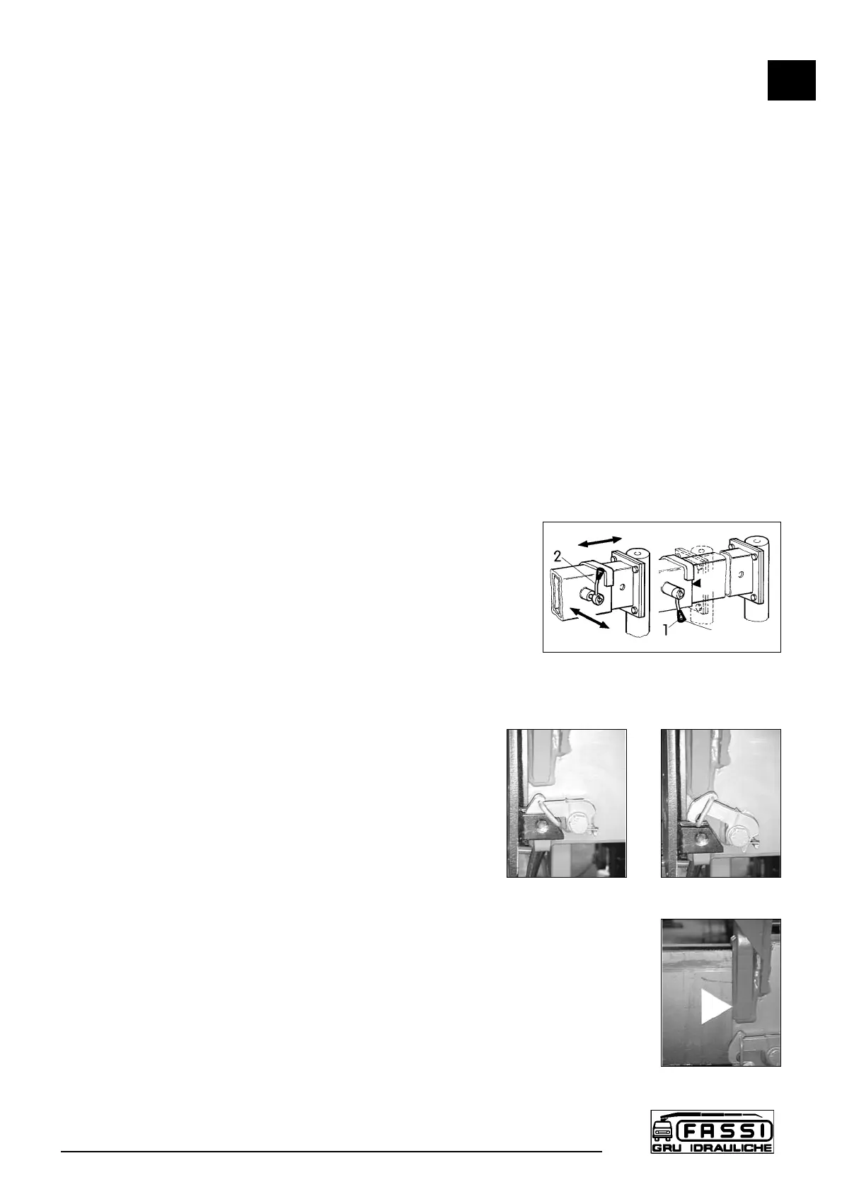
G2.1 Supplementary beam; manual extension
of the outrigger supports
(!) ATTENTION (!)
To manoeuvre the supports hands must only grab the handles
placed on the outrigger rams.
Position the lever B of the outrigger locking device from the
pos. 1 to the pos. 2 (released position) fig. 13.
Put the lever A of the outrigger security check from the posi-
tion of the fig. 14 to the one of the fig. 14a.
Extend the outrigger support from the base and position the
lever B to the pos. 1.
Extend the outrigger support till the coupling of the pin of the
lever B.
By the same sequence, repeat the operations described to extend the other
support.
(!) ATTENTION (!)
The complete extension of the outrigger support is visually indicated by the yellow
triangle which is found at the end of the beam. (Fig.14b)
The outrigger support is locked in position by the security pin; this will ensure the
complete extension of the outrigger support and the impossibility of accidental
movements.
G2
SUPPLEMENTARY BEAMS
F 170A
19
fig. 13
fig. 14
fig. 14a
fig. 14b
Lever B
 Loading...