To re-enter the outriggers repeat the operations previously described in reverse.
(!) WARNING (!)
Keep hands clear of automatic safety device (lever A from the position of the
fig. 14a to the one of the fig. 14).
Always make sure that the locking and security devices are correctly locked in
position so as to assure the impossibility of accidental movement.
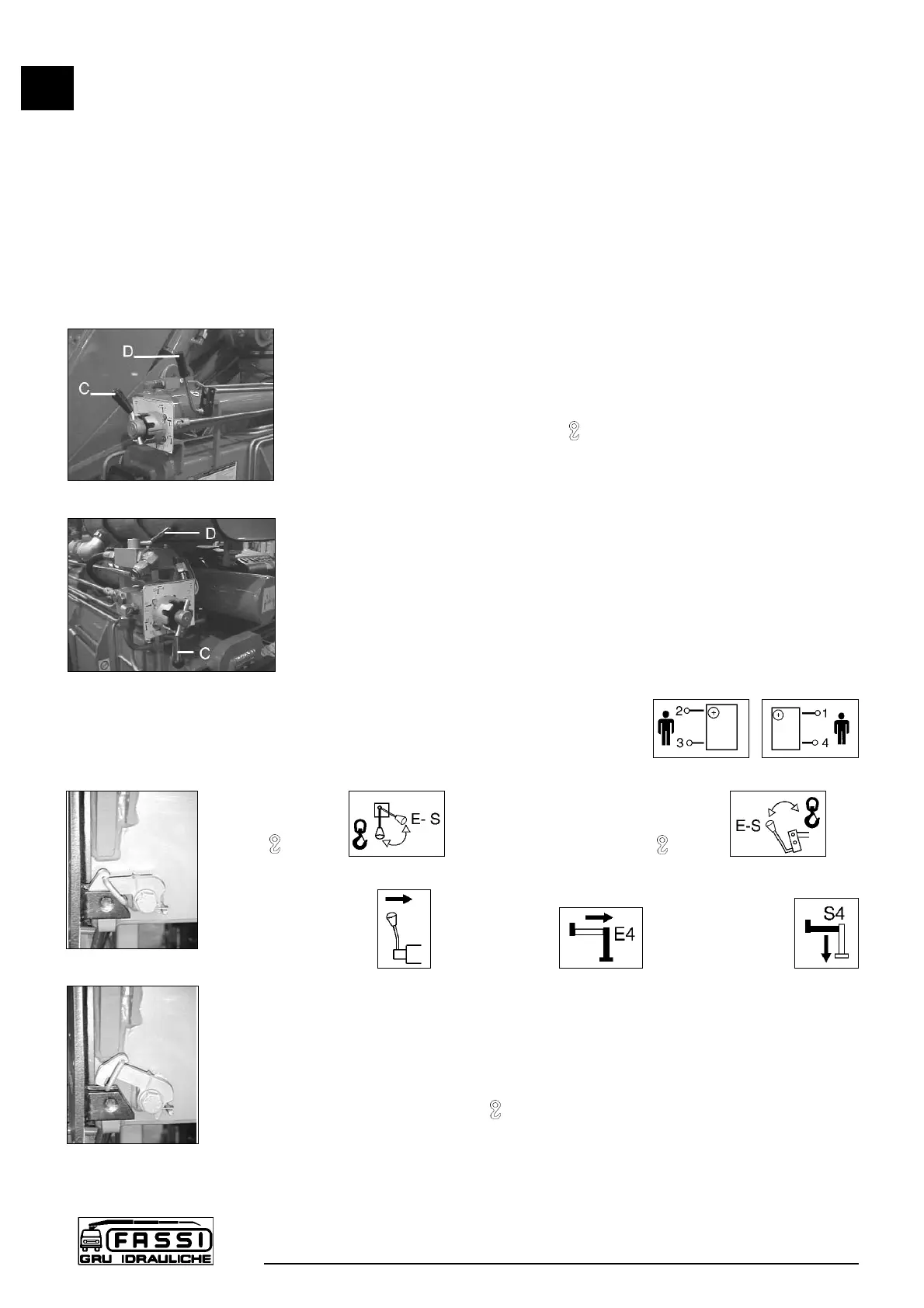
G2.2 Functions of control levers for stabilization
The controls to stabilize the vehicle are activated only from ground level and
on both sides of the crane base.
Lever function D - C (fig. 15-15a)
Levers D Control for deviator and deviator transmission
crane-outriggers ( - E/S ).
Levers C Control for multifunction deviator and multifunction
transmission for selecting and operating the supports
and the outrigger rams.
Operate the levers clockwise to select the control (multi-function deviator)
and in alternate direction to operate the required function (ram).
The deviator and the multifunction transmission are fitted with lever guide
which ensures accurate selection and operation.
NOTE The graphic symbols illustrated hereunder are marked on the
plates affixed on the deviator and on the dual or remote side
and indicate with the following symbolism
They indicate the position of the operator in relation
to the vehicle and the crane.
Lever D Lever D
Deviator D/control
- E/S Deviator - E/S
Lever C
Multifunction Hydraulic
Deviator and extension Outrigger
D/control control ram control
See Paragraph R0 Instruction and warning plates.
Disengage the locking devices of the outrigger supports by putting the levers A
from the position of the fig. 14 to the one of the fig. 14a.
Position lever D of oil diverter ( -E/S) on E/S.
G2.2
SUPPLEMENTARY BEAMS
F 170A
20
fig. 15
fig. 15a
fig. 14
fig. 14a
 Loading...