G2.3 Controls to stabilize the vehicle
The controls conform with the safety directives and enable the operator to activate
the lateral extension of the outrigger supports and rams only from the side where he
can visually check the operation.
- Exit of the outrigger support; position the lever C on the corresponding position
and then, activate the control.
- Outrigger ram descent; position the lever C on the corresponding position and
then, activate the control.
Note The levers, if placed on positions different from the ones indicated on
the plates on the deviator and the multifunction transmission do not
allow any operations because the safety devices have disabled them.
G2.4 Bilateral controls to stabilize the vehicle
The special fitment adopted allow the activation of the multifunction deviator only
from ground level and on both sides of the vehicle. Make sure that no one is or
transits in close proximity of the working area of the outriggers specially in the
case that the outrigger control is executed from the opposite side of the vehicle
(it is not possible visually check the operation).
- Exit of the outrigger support; position the lever C on the corresponding
position and then, activate the control.
- Outrigger ram descent; position the lever C on the corresponding position
and then, activate the control.
(!) ATTENTION (!)
During the stabilising operations, for each outrigger ram, it is recom-
mended to DESCENT the outrigger as the last manoeuvre.
(!) ATTENTION (!)
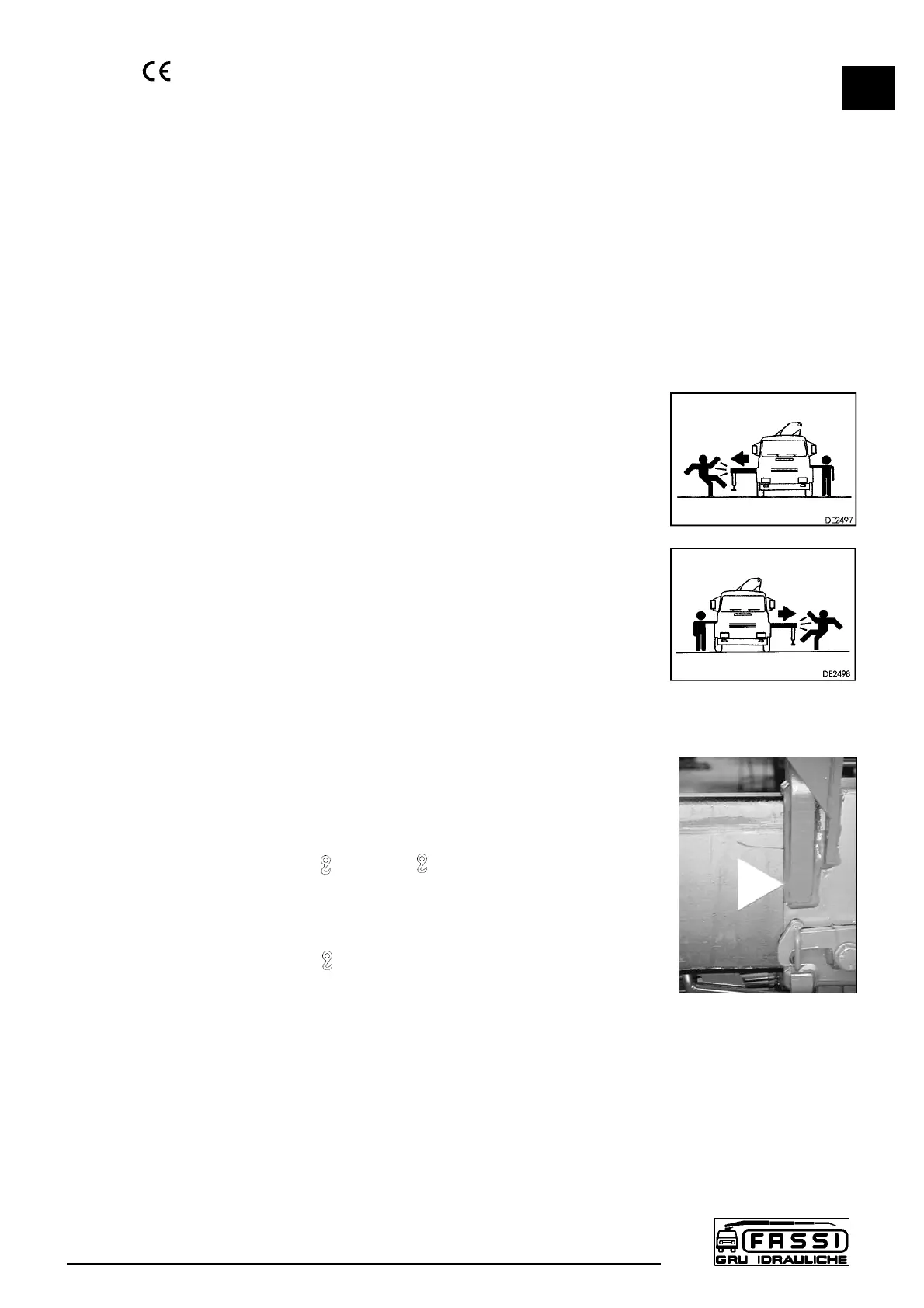
The complete extension of the outrigger supports is visually indicated by
the yellow triangles which are found at the end of the beam (Fig. 14b)
The stabilization has to be carried out with care and gradually keeping the
vehicle in horizontal levelled condition to prevent springs overloads and chas-
sis torsions.
To operate the crane controls, after having completed the descent and
stabilisation manoeuvres,
- Position lever D of oil diverter ( - E/S) on .
Manoeuvres for re-entry of the crane outriggers and supplementary
outriggers within the overall vehicle width after crane use.
- Position lever D of oil diverter ( - E/S) on E/S.
Repeat by inverting the sequence of the operations.
(!) WARNING (!)
Keep hands clear of automatic stop device of the outrigger supports
(lever A from the position of the fig. 14a to the one of the fig. 14).
(!) Always check that the outrigger supports, once in their rest position,
are locked in their seat by the safety devices, so as to assure the
impossibility of accidental movement. (fig. 14).
G2.3
SUPPLEMENTARY BEAMS
F 170A
21
 Loading...