Author – D. Rehe Feb 2020
Please refer to the F330 installation and commissioning manual for detailed wiring
connection instructions.
Wiring diagrams for various applications;
Standard Thyristor Wiring Diagram
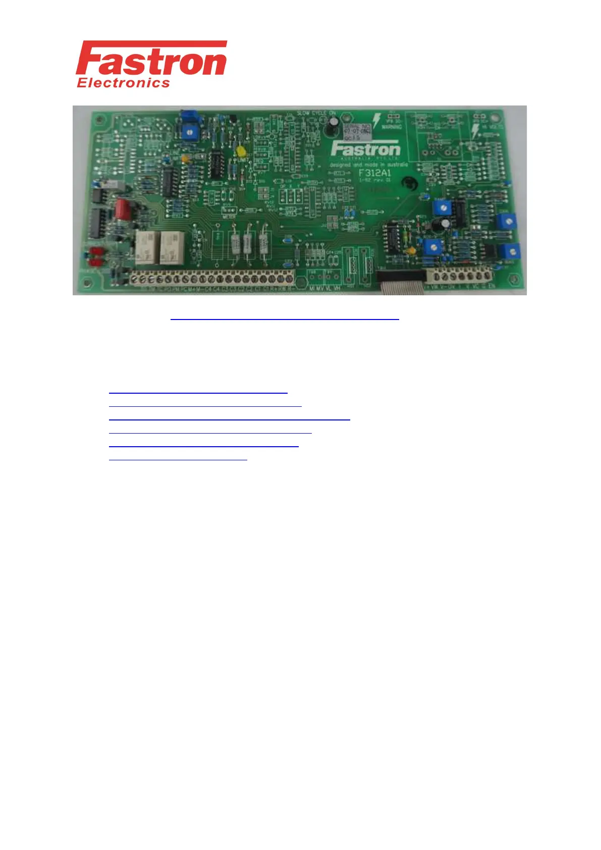
Control Card Wiring Diagram F311A1
New CCE option PCB1019-XX Wiring Diagram
Bridge Output Thyristor Wiring Diagram
Primary Transformer Wiring Diagram
Start Delta Wiring Diagram
Controller Identification
F330 Controllers are fitted with a single PCB marked F321A0 and F311A1. There should
be a silver sticker on the PCB with a serial number in the format of YY-MM-Serial #
Controller Options Identification
There are various options available for this controller which the most common are listed
and indicated by the following nomenclature
(FW) - Four Wire Load (Neutral) Critical for applications with return neutral
currents
(A) - A.C. Voltage Regulation
(C) - Current Limit and Trip
(CC) - Voltage Limit and current Trip. Current Source (A.C. Current Control)
(CCE) - Voltage Limit and current Trip. Current Source (D.C. Current Control)
(CE) - Current Limit and Trip (D.C.)
(F) - High Speed Fuses
(FW) - Four Wire Load
(MI) - Meter Output of Average Current (1mA for moving Coil Ammeter)
(MP) - Meter Output of Average Power (1mA for moving Coil Ammeter)