4-2
※For the relays marked with a ‘◤’ symbol in the special relay table(please refer to section 2.3)is write prohibited. In
addition, TU and TD contacts are not supported for those relays as well. The operands marked with a ‘*‘ symbol in the
table shown above should exclude those special relays.
4.2 Element Description
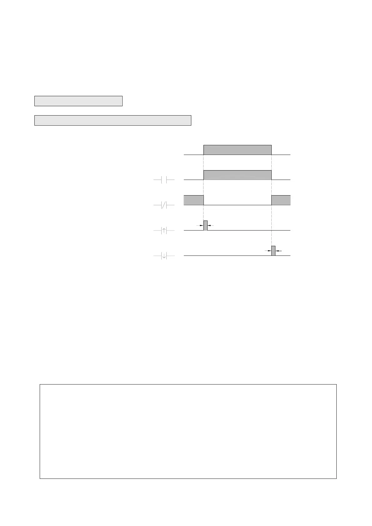
4.2.1 Characteristics of A,B,TU and TD Contacts
● Input X0 from the input terminal block
● A contact Element status
● B contact Element status
● TU contact Element status
● TD contact Element status
X0
X0
X0
X0
X0
ON
OFF
1
0
1
0
1
0
1
0
t
t
t: scan time
The waveform shown above reveals the function of A, B, TU and TD elements by exercising the external input X0 form
OFF to ON then OFF.
TU (Transition Up): This is the “Transition Up Contact”. Only a rising edge (0Æ1) of the referenced signal will turn on
this element for one scan time.
TD (Transition Down): This is the “Transition Down Contact”. Only a falling edge (1Æ0) of the referenced signal will
turn on this element for one scan time.
TU and TD contact will work normally as described above if the change of the status of the valid referenced operands
listed in the “Valid Range of the Operand of Sequential instructions” table are not driven by the function instructions.
Remark: For TU(TD) elements which operand is of relay will turn on after the first time the corresponding relay get
driven from 0 to 1(1 to 0). When the next time the corresponding relay get driven from 1 to 1(0 to 0) the
TD(TU) element will turn OFF. Care should be taken while there is a multiple coil usage situation existed
in the ladder program. This situation can be best illustrated at below. In the waveform we can see Y0 TU
element only turn on between ○
b
and ○
e
time which only the Y0 TU elements existed between rung 1
and rung 2 can detect the Y0 rising edge, while other Y0 TU elements out side these two ladder rungs will
never aware the occurrence of the rising edge. For the relays do not have the multiple coil usage in
ladder program, The ON status of corresponding TU or TD element can be sustained for one scan time,
but for relays which contrary to above, the turn on time will shorter than 1 scan time as illustrated at
below.