ENGLISH
A) Association procedure for radio communication through FS1
protocol (to be carried out only with the radio receiver of Fig.
2.3, art. 265-10):
• in the Configuration menu, select the “RADIO
Communication” tab;
• enable the “Activate radio transmission” parameter;
• select “FS1” in the “Radio protocol” parameter;
• in the “FS1 radio channel” parameter, choose a channel
among the available ones
1
;
• enable the “FS1 radio association” parameter to connect
the console to the scoreboard.
For more information on the association between Console-700
and the scoreboards with the FS1 protocol, read the radio
receiver manual, art. 265-10.
B) Association procedure for radio communication through FS2 protocol:
• in the Configuration menu, select the “RADIO Communication” tab;
• enable the “Activate radio transmission” parameter;
• select “FS2” in the “Radio protocol” parameter;
• if other Console-700 are used nearby, make sure that each console has a different value for the “Number
assigned to the console” parameter;
• Select the “Associate FS2 radio devices...” parameter and press the “SEARCH DEVICES...” button so that
the console can identify any nearby scoreboards; select the scoreboards you want to associate and press
the “ASSOCIATE!” button.
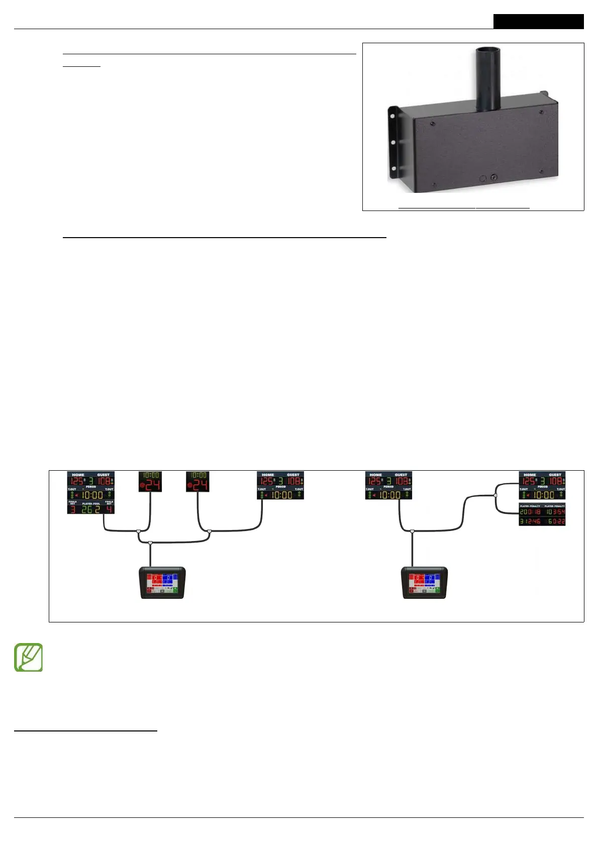
2.5.2 Wired communication
If you want to connect the Console-700 to the scoreboards by cable, you can use a standard straight-through
network cable, Cat. 5 UTP or Cat. 6 UTP, (EIA/TIA-568A/B).
Connect the cable to one of the two “Data Serial Output” connectors located on the back of the console.
Use the supplied splitters to connect all the installed LED boards. You can freely choose the connection
topology you prefer: “star”, “backbone”, “tree”, etc.
You can use indifferently one or both “Data Serial Output” outputs present on the back of the console (see Fig.
2.1); each output can control up to 8 LED boards at a distance of 200m.
If you have tailor-made cables or in environments where the presence of electric devices may cause disturbances
(such as electric motors, compressors, air conditioners, inverters, radio links, etc.), it is advisable to connect each
cable conductor as indicated in Fig. 2.5.
Avoid passing the cable through the same cable conductor used for the power grid cables.
1 The preset value for the radio channel is 20. The channel must be changed only in the following cases:
• if other Console-700s are present nearby; each console must have a different radio channel to avoid interference
between channels;
• if interference from other devices causes the scoreboards to work intermittently, it is advisable to select the “Measure
radio interferences” parameter and look for a channel free from interference; as an alternative, try the following series of
channels: 20, 15, 19, 23, 15, 18, 14, 22, 12, 21, 14, 22, 16, 13, 17.
FAVERO ELECTRONICS SRL
7 / 44
00308-M01-03-ML - Console-700 User Manual
Fig. 2.4: Examples of cable connections
Fig. 2.3: Radio receiver with FS1 protocol (art. 265-10)
 Loading...