Document Number:
MAN – FDDOCAPSULE
Revision Date:
12/09/2016
Page 12 of 37
© 2016 FDS Avionics Corp.
All Rights Reserved.
TECHNICAL SUPPORT
470-239-7421 or FDSAvionics.com
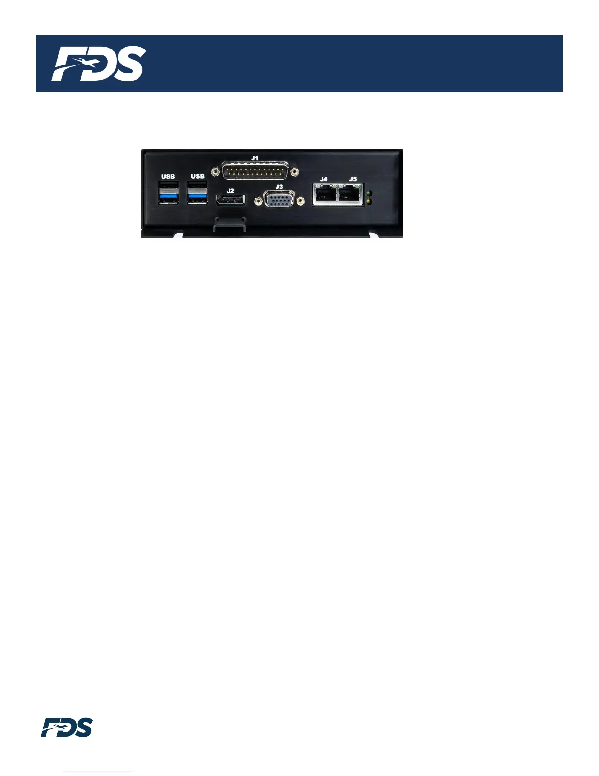
Rear Panel View
1. J1 – Power Connectivity
DB25 Male 28V DC Power, ARINC 429 and RS-232 for FMS/GPS Data, audio, and FDS CMS
interface via CAN.
2. USB 2.0 x (2) Black Connector
These ports can be used for a USB mouse/keyboard, thumb drives, point and shoot cameras,
and USB hard drives when adding additional content or configuring the moving map system.
3. USB 3.0 x (2) Blue Connector
These ports can be used for a USB mouse/keyboard, thumb drives, point and shoot cameras,
and USB hard drives when adding additional content or configuring the moving map system.
4. J2 – HDMI 1.4 (Refer to HDMI Connector Handling Section)
This connector is used to output the moving map to a bulkhead display with an HDMI input,
HDMI video converter, or an HDMI amplifier/switch. Use a plastic cable tie and the metal
bracket to secure HDMI connectors.
5. J3 – VGA
This connector is used to output the moving map to a bulkhead display with a VGA input, VGA
video converter, or a VGA amplifier/switch.
6. J4 – Ethernet Port
This RJ45 Connector is used to connect the do CAPSULE to the video streaming wireless
solution; the test Wi-Fi router or a permanently installed Wi-Fi solution. This Ethernet port has
a statically assigned IP address as defined in the FDS Avionics do CAPSULE pre-
configuration form. The default IP address is 192.168.0.100.
7. J5 – Ethernet Port
This RJ45 Connector is used to connect the do CAPSULE to a DHCP enabled router. This
Ethernet port has DHCP enabled for compatibility with any network. This port is also used for
Technical Support with FDS over the Internet.