Installation and Programming Instructions for the Serial Interface Module
3
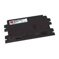
Serial Interface Module
Federal Signal www.fedsig.com
4. Connect the fuse end of the white wire from the supplied J1 cable harness as close as possible to
switched ignition power. Power should also be present in the cranking start position.
5. Connect the black and black/white wire from the supplied J1 cable harness to battery ground. Use
16AWG wire to extend cable length.
Quick Testing the Light Bar
Before programming and testing flash patterns, perform the LIGHT BAR TEST to ensure that all LEDs light
properly by following these steps:
NOTE: This feature does not test the STEADY BURN LED lightheads.
The SW2 Switch 3 must be in the UP position for the LIGHT BAR TEST (Table 1 below).
Applying 12 Vdc to the LIGHT BAR TEST control wire activates a test pattern that illuminates each head
sequentially. At the end of the sequence, the ALLEY and TAKEDOWN lights turn on.
For light bars with SpectraLux
®
Technology (Valor
®
and Vision
®
SLR), refer to the manual shipped with the
light bar for the test sequence. SCENE LIGHT is unavailable with this switch setting.
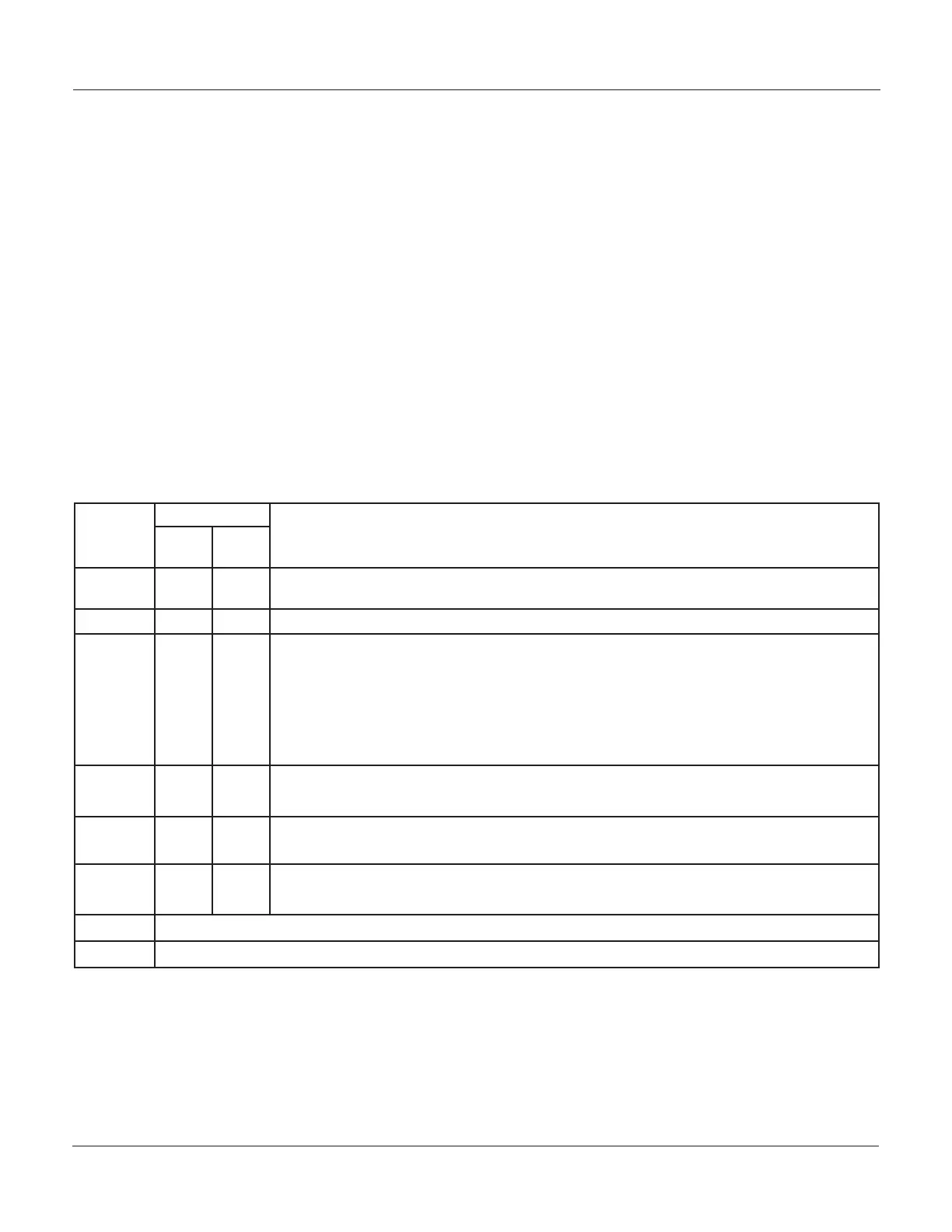
Table 1 SW-2 DIP switch settings in the Interface Module
SW2
Switch
Number
Switch Setting
SIgnalMaster
®
Function and Control Wires
(See the wiring harnesses on page 11 and 12.)
Up
(OFF)
Down
(ON)
1
1
X
X
FRONT/REAR LEDs cut o (deactivate) when 12 Vdc is applied their control wires.
FRONT/REAR LEDs enable (activate) when 12 Vdc is applied to their control wires.
2
X
Keep in OFF position
3 X
X
X
X
INTERSECTION is on when 12 Vdc is applied to blue/black wire.
LIGHT BAR TEST is on when 12 Vdc is applied to black/white/red wire.
SCENE LIGHT, LEFT is on when 12 Vdc is applied to blue/black wire.
SCENE LIGHT, RIGHT is on when 12 Vdc is applied to black/white/red wire.
NOTE: INTERSECTION and LIGHT BAR TEST are unavailable with the SCENE LIGHT
ON (down) switch setting. SCENE LIGHT activation is available only in light bars with
SpectraLux Technology (Valor and Vision SLR).
4
X
SignalMaster, EXTERNAL control
4
X
SignalMaster, INTERNAL control
5
X
Cycle forward through the selection of ash patterns
5
X
Cycle backward through the selection of ash patterns
6
X
Operation Mode
6
X
Program Mode
7 Switch for INTERSECTION operational settings (Table 2 on page 5)
8 Switch for INTERSECTION operational settings (Table 2)
 Loading...