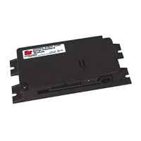
Installation and Programming Instructions for the Serial Interface Module
4
Serial Interface Module
Federal Signal www.fedsig.com
Programming the Flash Patterns
Before programming CUT OFF, program the light bar flash patterns. To access flash patterns, ensure that
SW2 Switch 1 is OFF.
NOTE: Cruise lights are also available in MODES 1 and 2.
IMPORTANT: The light bar must turn o before it displays the next flash pattern. To ensure that you do not
miss a pattern choice, push SW1 once, wait for the light bar to turn o, and then observe the next pattern.
To program the flash patterns:
1. Enter Program Mode.
a. Remove ignition power.
b. Turn ON (down position) Switch 6 on SW2.
c. Apply ignition power.
2. Program MODE 3.
a. Activate MODE 3 with +BAT.
b. Push and release SW1 until the flash pattern you want displays.
c. Remove +BAT from MODE 3.
3. Program MODE 2.
a. Activate MODE 2 with +BAT.
b. Push and release SW1 until the flash pattern you want displays.
c. Remove +BAT from MODE 2.
4. Program MODE 1.
a. Activate MODE 1 with +BAT.
b. Push and release SW1 until the flash pattern you want displays.
c. Remove +BAT from MODE 1.
5. Program INTERSECTION.
a. Activate MODE 1 and INTERSECTION with +BAT.
b. Push and release SW1 until the flash pattern you want displays.
c. Remove +BAT from MODE 1 and INTERSECTION.
6. Exit Program Mode.
a. Return Switch 6 on SW2 to the OFF (up) position.
b. Remove ignition power.
Programming Front/Rear Cut O
The active state for FRONT CUT OFF and REAR CUT OFF are not independent. As set at the factory, 12Vdc
must be applied for the front and rear light heads of the light bar to cut o. To initiate front and rear light
head ENABLE with the application of 12 Vdc, see “Front Cuto”and “Rear Cuto” in “Light Bar Functions
Activated via the CAT5 Cable (Excluding SignalMaster)” on page 6.
CUT OFF must be programmed after the MODE/INTERSECTION pattern. To enable pattern selection, SW2
Switch1 must be o (Table 1 on page 3).

 Loading...