Installation and Programming Instructions for the Serial Interface Module
6
Serial Interface Module
Federal Signal www.fedsig.com
Light Bar Functions Activated via the CAT5 Cable (Excluding SignalMaster)
LIGHT HAZARD: To be an eective warning device, this product produces bright light that can be
hazardous to your eyesight when viewed at a close range. Do not stare directly into this lighting
product at a close range, or permanent damage to your eyesight may occur.
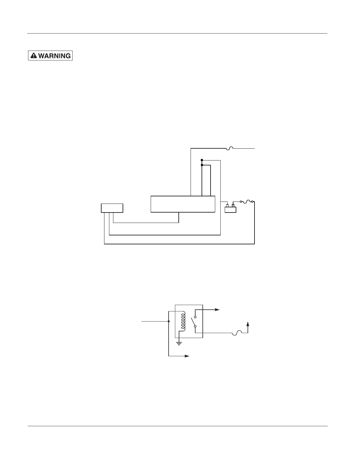
For a block wiring diagram, see Figure 2. For wiring schematics of the controller’s functions to the cable
harness supplied with the Interface Module, see Figure 4 (internal control) on page 10 and Figure5
(external control) on page 11. If additional wire is necessary for the harness (except ground), 22AWG
wire is adequate. The ground wires must be extended with wire that is 16AWG or better. All inputs are
active HIGH.
Figure 2 Wiring block diagram
Light Bar
FSC Serial Interface Module
Part #8583446 Reference
Serial, CAT5., Control Cable
-
+
Black 10 AWG
Red 10 AWG
User Supplied
Fuse 40 A
Battery
Black
White
Black / White
16 AWG
1 A
NOTE: Powering multiple devices with a common control lead may cause one or more units to briefly
remain functional after signal power is removed. For example, due to the high input filter capacitance,
a strobe supply can briefly supply the current required to signal a light bar function to remain ON. If
necessary, use a relay to isolate devices with large filter capacitors. See Figure 3 for the schematic.
Figure 3 Relay for isolating devices with large lter capacitors
Cudatrioptic
+12 V
Control Lead
(12 V Signal Activated)
Relay
Fuse
Strobe Supply
To activate a mode, apply 12 Vdc to a MODE control lead. There are three prioritized modes of operation
available, with MODE 3 as the highest priority. MODE 3 overrides MODE 2, and MODE 2 overrides MODE1.
One of the available flash patterns can be programmed to each mode input. To program a flash pattern, see
“Programming the Flash Patterns” on page 4.
 Loading...