Installation and Programming Instructions for the Serial Interface Module
9
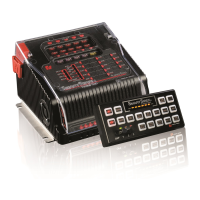
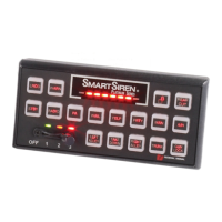
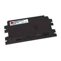
Serial Interface Module
Federal Signal www.fedsig.com
Wiring the Serial Interface Module to Power and Ground
AIRBAG DEPLOYMENT: Do not install equipment or route wiring in the deployment path of an
airbag. Failure to observe this warning will reduce the eectiveness of the airbag or potentially
dislodge the equipment, causing serious injury or death.
SEAT REMOVAL PRECAUTION: If a vehicle seat is temporarily removed, verify with the vehicle
manufacturer if the seat needs to be recalibrated for proper airbag deployment. Failure to follow
this warning cause serious injury or death.
To wire the Serial Interface Module to power and ground:
1. Connect the white wire from the supplied J1 cable harness on the Interface Module to a 1 A fuse.
2. Connect the fuse end of the white wire as close as possible to switched ignition power. Power should
also be present in the cranking start position.
3. Connect the black and black/white wire from the supplied J1 cable harness to battery ground. Use
16AWG wire to extend cable length.
4. Insulate spliced leads with twist-on wire connectors. Fold and seal unused leads. Use wire ties and hold-
downs for strain relief.
Wiring the SignalMaster
LIGHT HAZARD: To be an eective warning device, this product produces bright light that can be
hazardous to your eyesight when viewed at a close range. Do not stare directly into this lighting
product at a close range, or permanent damage to your eyesight may occur.
Depending on length, light bars have a four-, six-, or eight-head SignalMaster. Be sure to use the proper
controller to match the number of SignalMaster heads in the light bar.
If SignalMaster
®
operation is not initiated by a control head or external controller, the SignalMaster LED
heads flash according to the selected mode (1, 2, or 3) of operation.
External SignalMaster
The Interface Module can be configured from the factory default of Internal operation (see the next
section) to External operation. The Interface Module drives each SignalMaster head independently via an
external Federal Signal SignalMaster controller or an SS2000SM series siren. Either device will provide an
independent ground signal to illuminate each head.
For SignalMaster control functions wired to 12 Vdc for External Control, see Figure 5 on page 11.
Internal SignalMaster (Factory Default)
The Interface Module SignalMaster control leads are defined in Table 3. The SignalMaster can be configured
from External to Internal operation. +BAT applied to the specified control lead activates the internal
SignalMaster controller in the light bar. See Figure 4.
 Loading...