C02-1)
Bedienung Kombianschlag
Die Maschine ist mit einem Werkstück-
führungsanschlag ausgestattet.
Der Anschlag ist von 90°-45°
schwenkbar.
C02-1.1)
Anschlag schwenken
- Rändelschraube R1 und Klemmhe-
bel K lösen
- Gewünschten Winkel einstellen
(Skala S)
- Alle Klemmhebel schließen
C02-1.2)
Verschieben, Klemmen
- Exzenterhebel E lösen und Anschlag
verschieben.
- Falls notwendig Exzenterhebel E in
eine andere Bohrung umsetzten
C02-1.3)
Lineal umlegen
- Rändelschraube R1 lösen.
- Lineal L nach vorne herausziehen,
flach auf den Tisch legen und in der
Nut N einfädeln.
C02-1.4)
Feinverstellung
- Exzenterhebel E klemmen, Rändel-
schraube R2 lösen.
- Genaues Maß mit Verstellrad V ein-
stellen
- Rändelschraube R2 klemmen.
C02-1)
Operation of combination
fence
The machine is equipped with a fence
for guiding the workpiece.
The fence can be pivoted from
90° to 45°.
C02-1.1)
Pivoting stop
- Release the thumbscrew R1 and
clamping lever K
- Set the required angle (scale S)
- Close all clamping levers
C02-1.2)
Sliding, clamping
- Release cam lever E and move
fence.
- If necessary, place cam lever E in a
different bore.
C02-1.3)
Laying the straightedge flat
- Release the thumbscrew R1.
- Pull the straightedge L out forward,
place flat on the table and fit into
the groove N.
C02-1.4)
Fine adjustment
- Clamp the cam lever E, release the
thumbscrew R2.
- Set the precise dimension with the
adjuster wheel V.
- Tighten the thumbscrew R2.
C02-1)
Comando guidapezzo combi-
nato
La macchina è fornita di un guidapez-
zo.
Il guidapezzo può essere girato di
90°-45°.
C02-1.1)
Ruotare il guidapezzo
- Allentare la vite a testa zigrinata R1
e la leva di serraggio K
- Impostare l’angolo voluto (scala S)
- Chiudere tutte le leve di serraggio
C02-1.2)
Spostamento, serraggio
- Aprire la leva eccentrica E e sposta-
re il guidapezzo.
- Se necessario spostare la leva
eccentrica E in un altro foro
C02-1.3)
Spostamento della sagoma
- Allentare la vite zigrinata R1.
- Estrarre la sagoma L in avanti, met-
terla piatta sulla tavola e infilarla
nella scanalatura N.
C02-1.4)
Regolazione di precisione:
- Bloccare la leva eccentrica E, allen-
tare la vite a testa zigrinata R2.
- Impostare la quota esatta con la
ruota di regolazione V
- Stringere la vite zigrinata R2.
C02 V1/99 S1
- 2 -
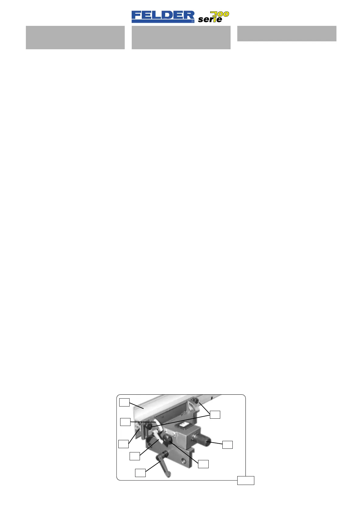
Abb 01
R1
V
N
S
L
K
E
R2
 Loading...

