C02-3.1) Winkelkorrektur
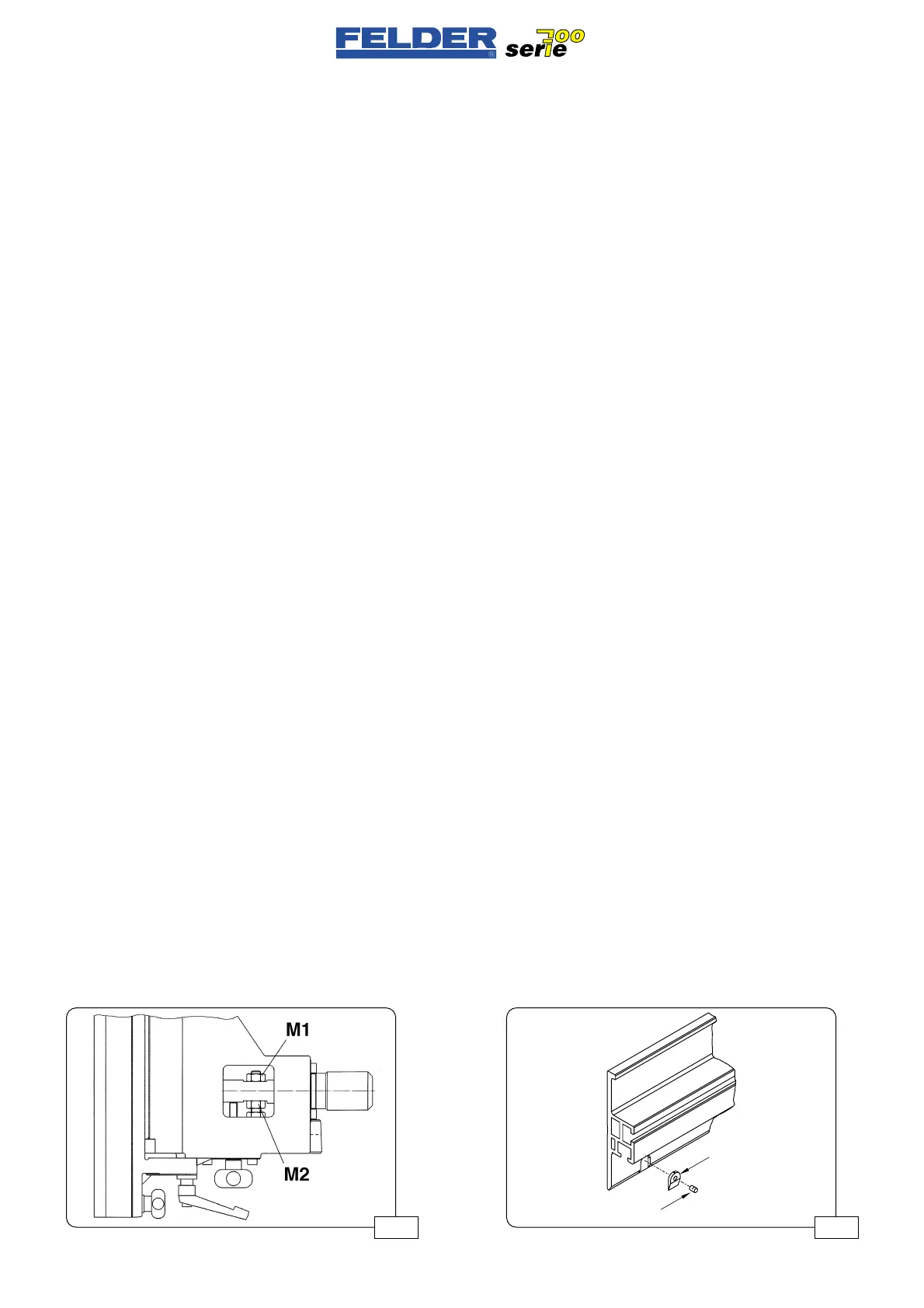
Siehe Abb. 04
Bei Kreissägearbeiten ist es sehr wich-
tig daß die Parallelität des Anschlagli-
neales zum Kreissägeblatt gegeben
ist, bzw. ein leichter Freischnitt von ca.
0,1 mm vorhanden ist .
Die Parallelität wird folgendermaßen
nachgestellt :
- Abdeckkappe entfernen
- Mutter M1 oder M2 lösen, je nach-
dem in welche Richtung das Lineal
nachjustieren werden soll.
- Durch Drehen der anderen Mutter
(M1 bzw. M2) wird nun die Paralle-
lität des Führungslineales zum Kreis-
sägeblatt eingestellt.
- Mutter M1 bzw. M2 wieder anzie-
hen.
- Einstellung durch einen Probeschnitt
prüfen.
- Das Werkstück darf zwischen
Anschlaglineal und Spaltkeil nicht
klemmen und das Kreissägeblatt
darf hinten auf dem hochlaufenden
Teil nicht stark nachschneiden.
C01-3.2) Gleitstücke
Siehe Abb. 05
Im Lineal des Abrichtanschlages sind
2 Stk. Gleitbacken aus Gleitkunststoff
eingelassen.
Diese Gleitstücke unterliegen einem
gewissen Verschleiß müssen bei Not-
wendigkeit nachgestellt oder ersetzt
werden.
Klemmschraube K öffnen und das
Gleitstück G einige Zehntel mm her-
ausschieben oder austauschen.
Klemmschraube K wieder anziehen.
C02-3.1) Angle correction
See fig. 04
It is very important for tablesaw work
that the fence straightedge be parallel
to the sawblade or that the blade cuts
slightly free by about 0,1 mm.
You set the fence parallel in the follo-
wing manner:
- Remove cover.
- Release nut M1 or M2, depending
on the direction in which the straigh-
tedge is to be adjusted.
- Turn the other nut (M1 or M2)
to adjust the straightedge parallel to
the sawblade.
- Retighten nut M1 or M2.
- Check the setting with a test cut.
- The workpiece must not pinch bet-
ween the fence straightedge and
splitter, and the sawblade must not
shave the workpiece at the trailing
edge of the cut.
C01-3.2) Sliding blocks
See fig. 05
Two plastic sliding blocks are installed
in the straightedge of the joiner fence.
These sliding blocks are subject to a
certain degree of wear and should be
adjusted or replaced as required.
Open clamping screw K and push the
sliding block G out by several tenths of
a mm, or exchange the block.
Retighten the clamping screw K.
C02-3.1) Correzione angolo
Vedere fig. 04
Nelle operazioni con sega circolare è
molto importante che esista un paral-
lelismo della sagoma guidapezzo ris-
petto alla lama della sega circolare,
e/o sia presente un leggero sottosqua-
dro di ca. 0,1 mm.
Il parallelismo viene regolato come
segue :
- Togliere la cappa di protezione
- Allentare il dado M1 o M2, a
seconda di quale direzione la sago-
ma debba essere regolata.
- Girando l’altro dado (M1 e/o
M2) viene ora regolato il parallelis-
mo della sagoma di guida rispetto
alla lama della sega circolare.
- Stringere nuovamente il dado M1
e/o M2.
- Controllare la regolazione con un
taglio di prova.
- Il pezzo non deve bloccarsi tra
sagoma guidapezzo e cuneo diviso-
re e la lama della sega circolare
non deve rifilare fortemente sulla
parte ad alta velocità.
C01-3.2) Elementi scorrevoli
Vedere fig. 05
Nella sagoma dell’guidapezzo pialla
a filo sono inseriti 2 pattini in plastica.
Questi elementi scorrevoli sono sotto-
posti a una certa usura e se necessa-
rio devono essere regolati o sostituiti.
Aprire la vite di serraggio K e spin-
gere fuori l’elemento scorrevole G di
alcuni decimi di mm o sostituirlo.
Stringere nuovamente la vite di ser-
raggio K.
- 4 -
C02 V1/99 S1
Abb 04
 Loading...

