EasyManua.ls Logo

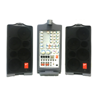
Fender PASSPORT PD-150 PLUS User Manual

Fender PASSPORT PD-150 PLUS
50 pages
To Next Page IconTo Next Page
Page #1 background imageLoading...
Page #1 background image
PASSPORT
®
PD-150 PLUS
(This is the model name for warranty claims)
Fender Musical Instruments Corporation, 8860 East Chaparral Road Suite 100 Scottsdale, AZ 85250
Issued: October, 2006
p/n 069-3005-000
SERVICE MANUAL
ATTENTION:
WARRANTY SERVICE PROCEDURES
Warranty field service of the Passport PD-150 Plus will be limited to replacement of
defective PCB Assemblies and all other parts not
marked as “REF” in the Parts List. Non-
Warranty repairs can of course be to the component level at the Service Centers
discretion. For non-warranty component level repairs all parts listed as “REF” in the Parts
List must be sourced from suppliers other than FMIC.
Question and Answer IconNeed help?

Do you have a question about the Fender PASSPORT PD-150 PLUS and is the answer not in the manual?

Fender PASSPORT PD-150 PLUS Specifications

General IconGeneral
BrandFender
ModelPASSPORT PD-150 PLUS
CategorySpeakers
LanguageEnglish

Summary

Fender Passport PD-150 Plus Service Manual

Warranty Service Procedures

Details warranty field service limitations and non-warranty repair sourcing requirements for the PD-150 Plus.

Fender Passport PD-150 Plus Specifications

Product Specifications

Provides technical details including frequency response, distortion, power output, input impedance, and physical dimensions.

Service Manual: Disassembly and Repair Notes

PD-150+ Disassembly Procedures

Step-by-step instructions for dismantling the PD-150+ cabinets and various PCB assemblies.

Fender PCB Exchange Policy

Fender Passport PD-150 Plus Circuit Description

SMPS PCB Module Description

Explains the function of the Switched-Mode Power Supply (SMPS) module and its output voltages.

Fender Passport PD-150 Plus Diagram Reference

Schematic Diagrams Overview

Lists all available schematic diagrams for the CD Servo, LCD, D-AMP, Input, Mixer, DSP Reverb, and SMPS PCBs.

Fender Passport PD-150 Plus Wiring Diagram

Wiring Diagram: Board Interconnections

Illustrates the wiring connections between the main PCB assemblies (Servo, LCD, Input, SMPS, Amp, Mixer, Output, DSP Reverb).
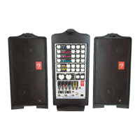
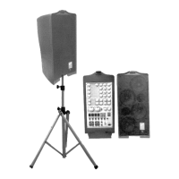
Fender Passport PD-150 Plus Front Panel Exploded View

Fender Passport PD-150 Plus Power Supply Exploded View

Fender Passport PD-150 Plus Speaker Assembly Exploded View

Fender Passport PD-150 Plus Main Unit Exploded View

Related product manuals