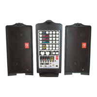
Do you have a question about the Fender Passport PD-250 and is the answer not in the manual?
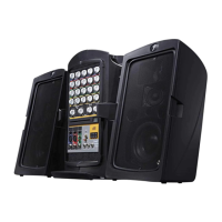
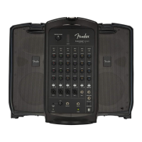
| Type | Portable PA System |
|---|---|
| Power Output | 250 Watts |
| Speaker Configuration | 2-way |
| Built-in Mixer | Yes |
| Outputs | XLR |
| Speakers | 1" tweeter |
Technical parameters including frequency response, distortion, gain stages, and power output.
Details the mixer section's components and signal flow, including preamplifiers and tone controls.
Explains the digital reverb IC, op-amps, and foot switch control for the reverb function.
Describes the signal processor and EQ circuits integrated with the power amplifier section.
Explains the power amplifier's stages, including FET muting, differential circuit, driver stage, and output section.
Details the SMPSU's operation, protection circuits, and mains input voltage settings.
Lists updates and changes made to the mixer, power amplifier, and reverb circuits.
Lists parts for the Mixer Section Printed Circuit Board Assembly.
Lists parts for the 1/4" Phone Jack Section Printed Circuit Board Assembly.
Lists parts for the Mic/Line Amplifier Section Printed Circuit Board Assembly.
Lists parts for the Digital Reverb Section Printed Circuit Board Assembly.
Lists parts for the Stereo Power Amplifier Section Printed Circuit Board Assembly.
Lists parts for the Amplifier Protection Circuit Printed Circuit Board Assembly.
Lists parts for the RCA Tape Output Printed Circuit Board Assembly.
Lists parts for the LED Indicators Printed Circuit Board Assembly.
Lists parts for the Wireless REG Assembly Printed Circuit Board Assembly.
Lists parts for the Switch Mode PSU Circuit Printed Circuit Board Assembly.
Lists parts for the Speaker Cabinet Assembly.
Lists various packing accessories and their country of origin/type.
Lists complete or stuffed PCB assemblies for quick replacement.
Circuit diagram for the Microphone input section.
Circuit diagram for the Mixer section.
Circuit diagram for the Power Amplifier section.
Circuit diagram for the Reverb section.
Component and copper side layout for the Input Section PCB.
Component and copper side layout for the Rev/Protection PCB.
Component and copper side layout for the Power Amplifier Section PCB.
Copper side layout for the Mixer Section PCB.
Component side layout for the Mixer Section PCB.
Layout views for Regulate, RCA, and LED PCBs.
Exploded view of the main unit assembly, showing component parts and their placement.
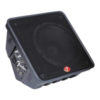
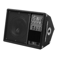
Exploded view of the speaker box assembly, detailing its components.
Exploded view of the handle assembly, showing its parts.
Exploded view of the packing assembly, illustrating included items.
Exploded view of the mixer assembly and its components.
Exploded view of the power amplifier and SMPSU modules.