5
Ferm
EN
If the moulded 3-pin plug attached to the unit is
damaged and needs replacing, it is important that
it is correctly destroyed and replaced by an
approved BS 1363/5A fused plug and that the
following wiring instructions are followed.
The wires in the mains cable are coloured in
accordance with the following code:
blue neutral
brown live
As the colours of the wires in the mains cable of
the unit may not correspond to the coloured
markings identifying the terminals in the plug,
proceed as follows:
- The wire which is coloured blue must be
connected to the terminal which is marked with
theletterNorcolouredblack.
- The wire which is coloured brown must be
connected to the terminal which is marked with
the letter L or coloured red.
TECHNICAL DATA
BSM1023
Mainsvoltage V~ 230
Mainsfrequency Hz 50
Powerinput W 950
No-loadspeed m/min 380
Sandingbeltsize mm 75x533
Sandingpadsize mm 76x135
Protectionclass IP20
Weight kg 3.65
NOISE AND VIBRATION
BSM1023
Sound pressure (L
pa
) dB(A) 92.3
Acoustic power (L
wa
) dB(A) 103.3
Uncertainty (K) dB(A) 3
Vibration(maingrip) m/s
2
2.31
Uncertainty (K) m/s
2
1.5
2
Wear hearing protection.
Vibration level
The vibration emission level stated in this
instruction manual has been measured in
accordancewithastandardisedtestgiveninEN
60745;itmaybeusedtocompareonetoolwith
another and as a preliminary assessment of
exposure to vibration when using the tool for the
applications mentioned
- using the tool for different applications, or with
different or poorly maintainted accessories,
maysignicantlyincreasetheexposurelevel
- the times when the tool is switched off or when
it is running but not actually doing the job, may
signicantlyreducetheexposurelevel
Protect yourself against the effects of vibration by
maintaining the tool and its accessories, keeping
yourhandswarm,andorganizingyourwork
patterns
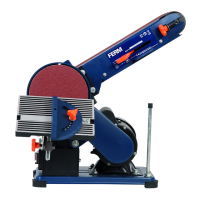
Your belt sander has been designed for rough
sanding applications on wood, metal, plastics and
painted surfaces.
1. On/offswitch
2. Lock-on button
3. Sanding pad
4. Sanding belt roller
5. Clamping lever for sanding belt
6. Centring knob for sanding belt
7. Maingrip
8. Auxiliarygrip
9. Dustbagconnection
10. Carbonbrushholder
11. V-beltcover
ASSEMBLY
3
Before assembly, always switch off the
machine and remove the mains plug
from the mains.
Mounting and removing the sanding belt
Mounting
● PlacethemachineonitssidewiththeV-belt
cover (11) facing downwards.
● Releasetheclampinglever(5).
● Mountasandingbelt(12)withtherequired
grainsizearoundthesandingpad(3)andthe
sandingbeltrollers(4).Makesurethatthearrow
on the inside of the sanding belt points in the
same direction as the arrow on the housing.
- Useacoarsesandingbelt(grain50)for
sanding rough, uneven surfaces.
- Useamediumsandingbelt(grain80)for
removing the remaining scratches from the
coarse sanding belt.