5
EN
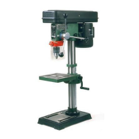
BENCH PILLAR DRILL
TDM1026
Thank you for buying this Ferm product.
By doing so you now have an excellent product,
delivered by one of Europe’s leading suppliers.
All products delivered to you by Ferm are
manufactured according to the highest standards
of performance and safety. As part of our
philosophy we also provide an excellent customer
service, backed by our comprehensive warranty.
We hope you will enjoy using this product for
many years to come.
Read the operating instructions carefully
before using this device. Familiarise
yourself with its functions and basic
operation. Service the device as per the
instructions to ensure that it always
functions properly. The operating
instructions and the accompanying
documentation must be kept in the
vicinity of the device.
1. MACHINE INFORMATION
Technical specifications
Voltage 230 V~
Frequency 50 Hz
Power consumption (S2) 350 W
No load speed 500 - 2500/min
Number of speeds 5
Chuck capacity 13 mm
Weight 14 kg
Lpa (Sound pressure level) 71 dB(A) K=3
Lwa (Sound power level) 84 dB(A) K=3
Vibration <2.5 m/s2
Vibration level
The vibration emission level stated in this
instruction manual has been measured in
accordance with a standardised test given in
EN 61029; it may be used to compare one tool
with another and as a preliminary assessment of
exposure to vibration when using the tool for the
applications mentioned.
- using the tool for different applications, or with
different or poorly maintainted accessories,
may significantly increase the exposure level.
- the times when the tool is switched off or when
it is running but not actually doing the job, may
significantly reduce the exposure level.
Protect yourself against the effects of vibration by
maintaining the tool and its accessories, keeping
your hands warm, and organizing your work
patterns.
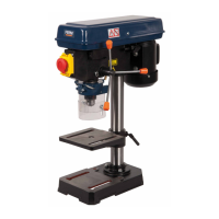
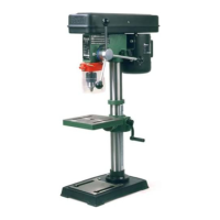
Description
The numbers in the text refer to the diagrams on
pages 2-4.
1. On/off switch
2. Depth limiter
3. Chuck guard
4. Motor
5. Drill depth handle
6. Table adjustment
7. Emergency stop switch
8. Fixing screw
9. Chuck
10. Table holder
11. Column
12. Bolts
13. Footplate
14. Upper V-belt cover
15. Lower V-belt cover
16. Cover lock
17. Motor plate
18. Belt tension lock
19. Table
20. Hexagonal screw
21. Spindle
22. Chuck key
Check first whether or not the delivery has been
damaged by transport and/or whether all the
parts are present.
2. SAFETY INSTRUCTIONS
Explanation of symbols
The following pictograms are used in these
instructions for use:
Denotes risk of personal injury, loss of life
or damage to the tool in case of non-
observance of the instructions in this
manual.