EasyManua.ls Logo

Fermax Citymax Universal User Manual

Fermax Citymax Universal
6 pages
To Next Page IconTo Next Page
Page #1 background imageLoading...
Page #1 background image
Fermax Citymax Universal
Terminals
1 Lock
2 Speech Out (Mic)
3 Common
6 Speech In (Speaker)
4 Call
Note : Jumpers must be set correctly
otherwise call tone may not work and you
may only get speech 1 way (see instructions
below)
IMPORTANT NOTE :
1) Before replacing the handset make note of the wires to each terminal on the existing unit (an easy way
is to cut each core off leaving a piece of the insulation in place with colour visible) twist unused cores
together (so you know they are not used, do not short them out).
2) Some older systems will have cable with one coloured core and a solid white core in this case mark
each core with a marker or tape.
3) Some systems may have loop on wiring, you will have 2 cables into your handset (make
sure any joins
remain, as these may be serving other flats on the system).
© 2010 www.intercomsrus.com

Other manuals for Fermax Citymax Universal

Question and Answer IconNeed help?

Do you have a question about the Fermax Citymax Universal and is the answer not in the manual?

Fermax Citymax Universal Specifications

General IconGeneral
BrandFermax
ModelCitymax Universal
CategoryIntercom System
LanguageEnglish

Summary

Terminals

Terminal 1 Lock

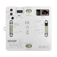
Defines terminal 1 for the lock connection.

Terminal 2 Speech Out (Mic)

Defines terminal 2 for speech output (microphone).

Terminal 3 Common

Identifies terminal 3 as the common connection.

Terminal 4 Call

Identifies terminal 4 for the call function.

Terminal 6 Speech In (Speaker)

Defines terminal 6 for speech input (speaker).

IMPORTANT NOTE

Wire Handling Advice

Note wire positions and handle unused cores before replacing handset.

Older System Cable Marking

Mark cores on older systems with single colored and solid white cores.

Loop Wiring Considerations

Verify loop wiring and existing joins for multiple handset systems.

COMPATIBILITY TABLE

INSTALLATION INSTRUCTIONS

Mounting and Wiring

Details on wall mounting, fixing points, and wire passage.

Connection Guide

Instructions for connecting terminals matching symbols.

REMARKS

TECHNICAL FEATURES

Wiring Diagram 1 Way Basic Audio

Wiring Diagram 5 Wire Audio System

Wiring Diagram 5 Wire Audio with 2 Entrances

Related product manuals