Pag 13
Kit Halo & iLoftKit Halo & iLoft
Kit Halo & iLoftKit Halo & iLoft
Kit Halo & iLoft
Kit Halo & iLoftKit Halo & iLoft
Kit Halo & iLoftKit Halo & iLoft
Kit Halo & iLoft
PROG
.
T
A+
-
LVF2
+
Ct MF1 V
Ct + MVMVF1
T
A+ L-F2
PROG.
SW3
SW5
SW4SW2
SW1
NOK
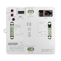
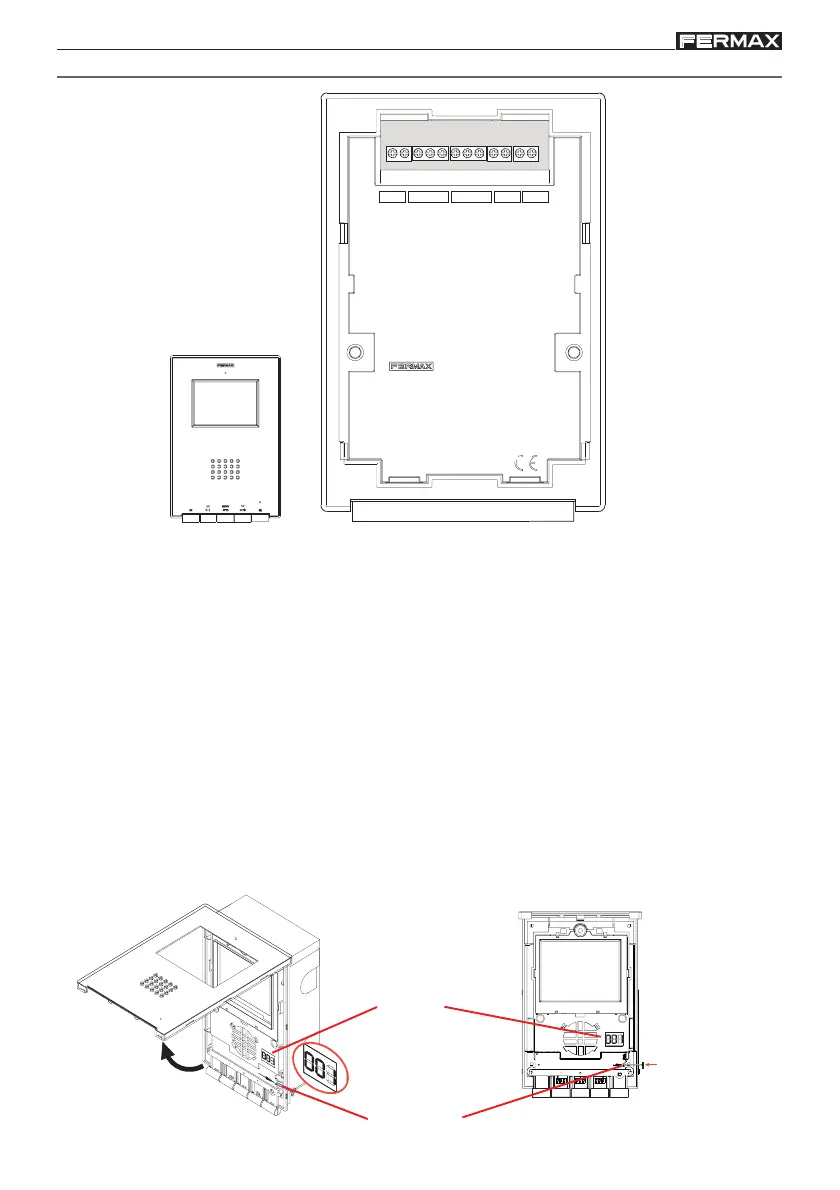
Conectores Monitor:
• Bornas de video, (coaxial).
V: vivo
M: malla
Ct: activación telecamara (10 Vdc)
• Bornas de Conexión:
+, -: alimentación (18 Vdc).
L: bus de datos.
F1, F2: funciones adicionales (salida negativo «-»).
T, -: Conexión pulsador de llamada puerta vivienda
A, +: Conexión prolongador de llamada ref.2040, activador luces y timbres ref. 2438, etc...
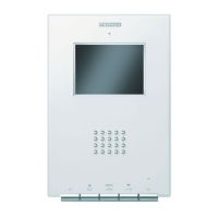
Display de programación: muestra el número ADS de llamada programado.
Botón PRG: botón para entrar en modo programación.
Display
Botón PRG
Pulsar para
entrar en
programación
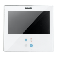
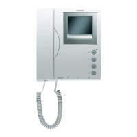
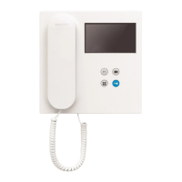
DESCRIPCIÓN MONITOR ILOFT