Pag 8
Kit Halo & iLoftKit Halo & iLoft
Kit Halo & iLoftKit Halo & iLoft
Kit Halo & iLoft
Kit Halo & iLoftKit Halo & iLoft
Kit Halo & iLoftKit Halo & iLoft
Kit Halo & iLoft
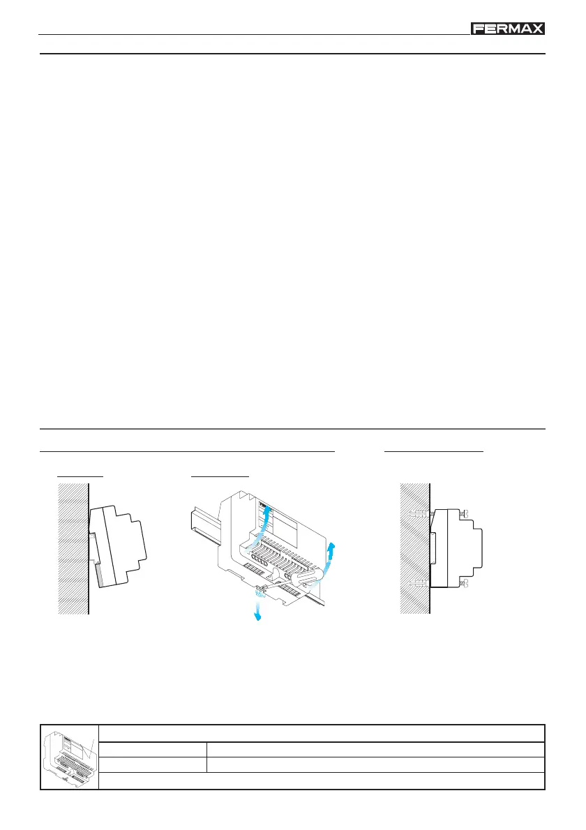
Dismantling
DIN rail installation
Assembly
Fixng with screw bolts
+18V 1.5A
50
-60 H
z. 50VA
M
A
X
.
12V 1A
F
U
E
N
T
E
A
L
IM
E
N
T
A
C
IO
N
K
IT
D
I
G
I
T
A
L
M
A
D
E
I
N
S
P
A
I
N
NOTES:
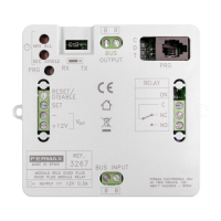
OVERLOAD
Maxium current exceeded LED indicator.
ON
On + OVERLOAD LED blinking indicates short circuit.
POWER SUPPLY (LEDs)
On LED
+
1
8
V
1
.
5
A
5
0
-6
0
H
z.
5
0
V
A
M
A
X
.
F
U
E
N
T
E
A
L
I
M
E
N
T
A
C
I
O
N
K
I
T
D
I
G
I
T
A
L
M
A
D
E
I
N
S
P
A
I
N
O
N
O
V
E
R
L
O
A
D
O
N
O
V
E
R
L
O
A
D
POWER SUPPLY INSTALLATION
STEPS FOR INSTALLATION
1. Install the Kit equipment as shown in this manual.
2. Connect the system to the power supply.
3. Program the video door entry monitor.
See section: «Programming the monitor».
4. Program the access control function: activate the proximity cards.
See section: «Panel configuration».
5. Adjust the entry panel and home monitor as required: adjust the opening times,
brightness, colour, etc..
See sections:
- «Panel settings».
- «Panel configuration».
- «Monitor Settings».