Pag. 23
Technical Book
MDS-ADS
MDS-ADS
Supply
12 Vdc ± 10% (CN1).
18 Vdc ± 10% (CN2).
If either of the two feeders is off the circuit does not operate.
Consumption
12 Vdc: 15 mA in standby.
60 mA in operation.
18 Vdc: 25 mA in standby.
80 mA in operation.
Operating Temperature
0 ÷ +60 ºC with H.R. 90% without condensation.
Installation
Interior fitted closet or building interior.
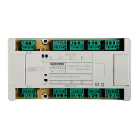
Connection terminals
CN1: MDS Installation.
+,-: Supply 12 Vdc.
D1,D2: Decoder bus data. RS-485.
2,6: MDS Audio panels. 2 -> to outdoor panel, 6 -> to apartment.
CN2: ADS Installation.
+,-: 18 Vdc Supply.
L: ADS Bus and Audio Data.
Ct: Video activation. 0v in standby, 12Vdc with decoder running.
Max. 100 mA.
S: Video switcher activation. Collector open active with decoder running. Max. 100mA.
CN3: PC-Decoder interface connection for programming from PC.
LED Signal.
- Off: Indicates that the decoder has not yet been programmed.
- On: Indica that the decoder is in programming mode.
- 1 blink every 3 seconds: Indicates that the the decoder is programmed and in night mode (no
guard units are active).
- 2 blinks every 3 seconds: Indicates that decoder is programmed and in day mode (guard unit
active).
TECHNICAL FEATURES