5
NOTE: See diagrams (6-7) at the end of this manual.
1). Power-on within 5 seconds, short-circuit S2 up to 3 seconds, the IN-USE indicator
fl ash.
2). Short-circuit S1 up to 3 seconds, and the IN-USE indicator always light.
3). Short-circuit again S2, at this time,the short-circuit time equal to unlock delay time.
(the IN-USE indicator flashes once per second, Less than two seconds by one
second calculation; The maximum setting time is 30 seconds.)
4). After S2 released, saved unlock delay, and exit the setting.
GND NO COM NC
DT-RLC
2-WIRE SYSTEM
12V S2 S1 GND
POWER IN-USE
BUS BUS
RISER
1
2
3
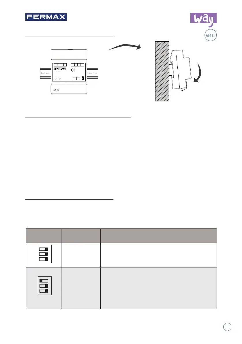
DIN Rail Mounting
The DIP switch in the back of the panel is used to set the address of the relay. Please
refer to the followings for more detail informations about the DIP settings:
DIP settings for lock.
3.
Unit Mounting
4.
How to set the unlock delay time
5.
DIP Switch Setting
12V S2 S1 GNDGND NO COM NC
BUS BUS
REF 1418
MODULO RELE WAY
WAY RELAY MODULE
POWER IN-USE
RISER
RoHS
Compliant
-2-
DIP Bit State Descriptions
OFF,OFF,OFF Lock 1 of the panel 1.
OFF,OFF,ON
Relay for control the second lock of the panel 1:
- Without external power supply (Wiring diagram 6).
- With external power supply (Wiring diagram 7):
• A) With Electric lock type
• B) With Magnetic lock type
1
23
ON
1
23
ON