© Ferno-Washington, Inc. / March 2016 / 234-3621-00
13
6
Features
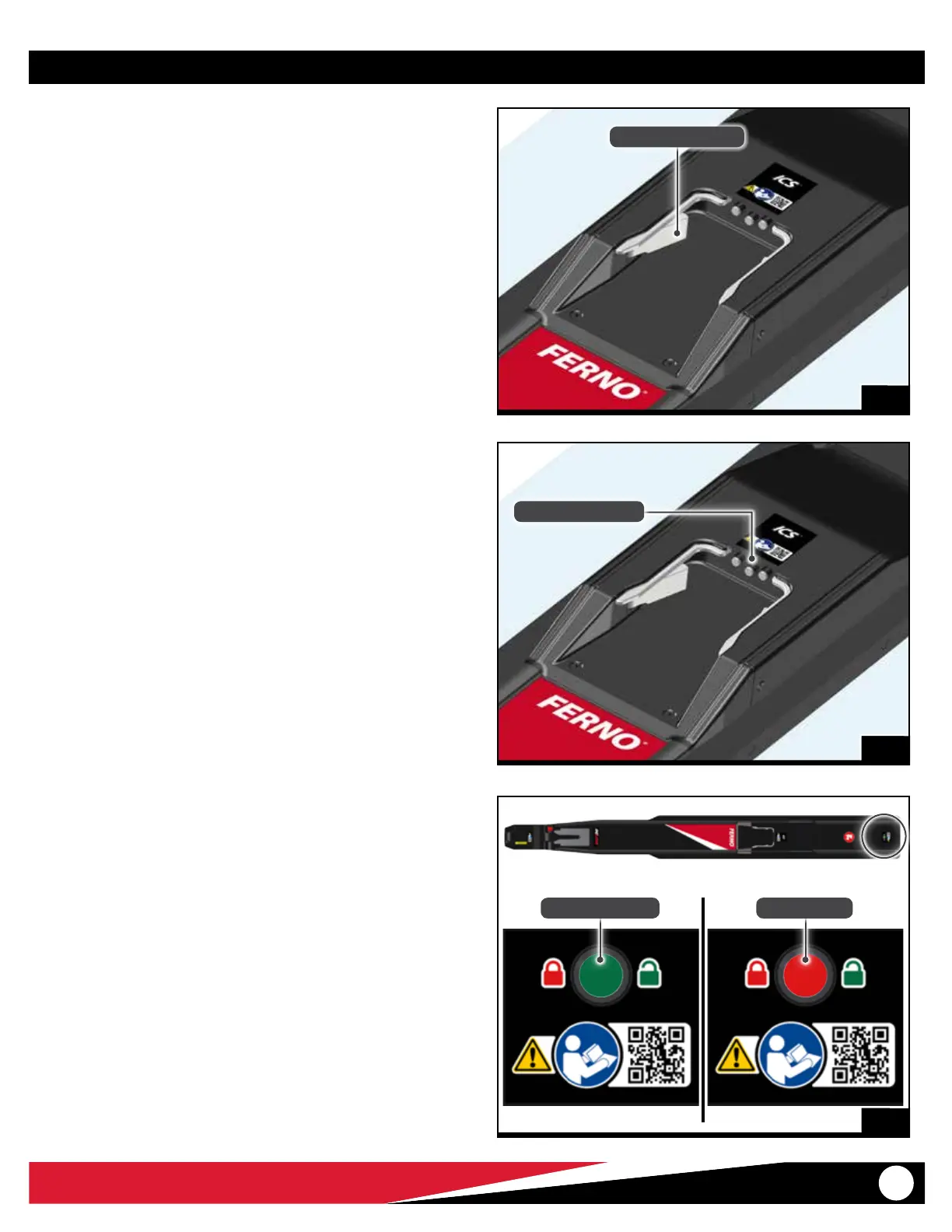
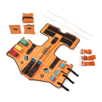
4.5 Integrated Charging System (ICS®)
The Ferno® Integrated Charging System (ICS®) is located near the center
of the fastening system (Figure 5). When a Ferno® iN∫X is locked in the
fastening system and the ICS is connected and powered, the ICS will:
● disable powered operation of the iN∫X
● charge the iN∫X battery
The ambulance ignition, inverter, and/or outlet switch may need to be
turned ON to supply electrical power to the ICS.
4
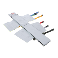
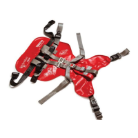
4.6 Floor Lock Indicator Window
The oor lock indicator window is located at the end of the fastening
system (Figure 6) and helps verify that the fastening system is secured
to the ambulance oor.
The indicator window is fully red when the fastening system is properly
locked to the oor.
If the indicator window shows any portion of green (unlocked), the
fastener is not properly secured to the ambulance oor.
The upper fastener is removable from the oor for cleaning. See
“Removing the Fastening System from the Floor for Cleaning” on page
17 and “Attaching the Fastening System to the Ambulance Floor” on
page 18.
5
ICS Charging Contacts
Fastening Post Lock
Not Locked to Floor Locked to Floor
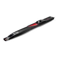
4.4 Fastening-Post Lock
The fastening-post lock is located near the center of the fastening
system (Figure 4). It captures the loading-end post of the compatible
Ferno product during the loading process and securely locks it in the
fastening system during vehicle transport. See “Using the Fastening
System” on page 14.