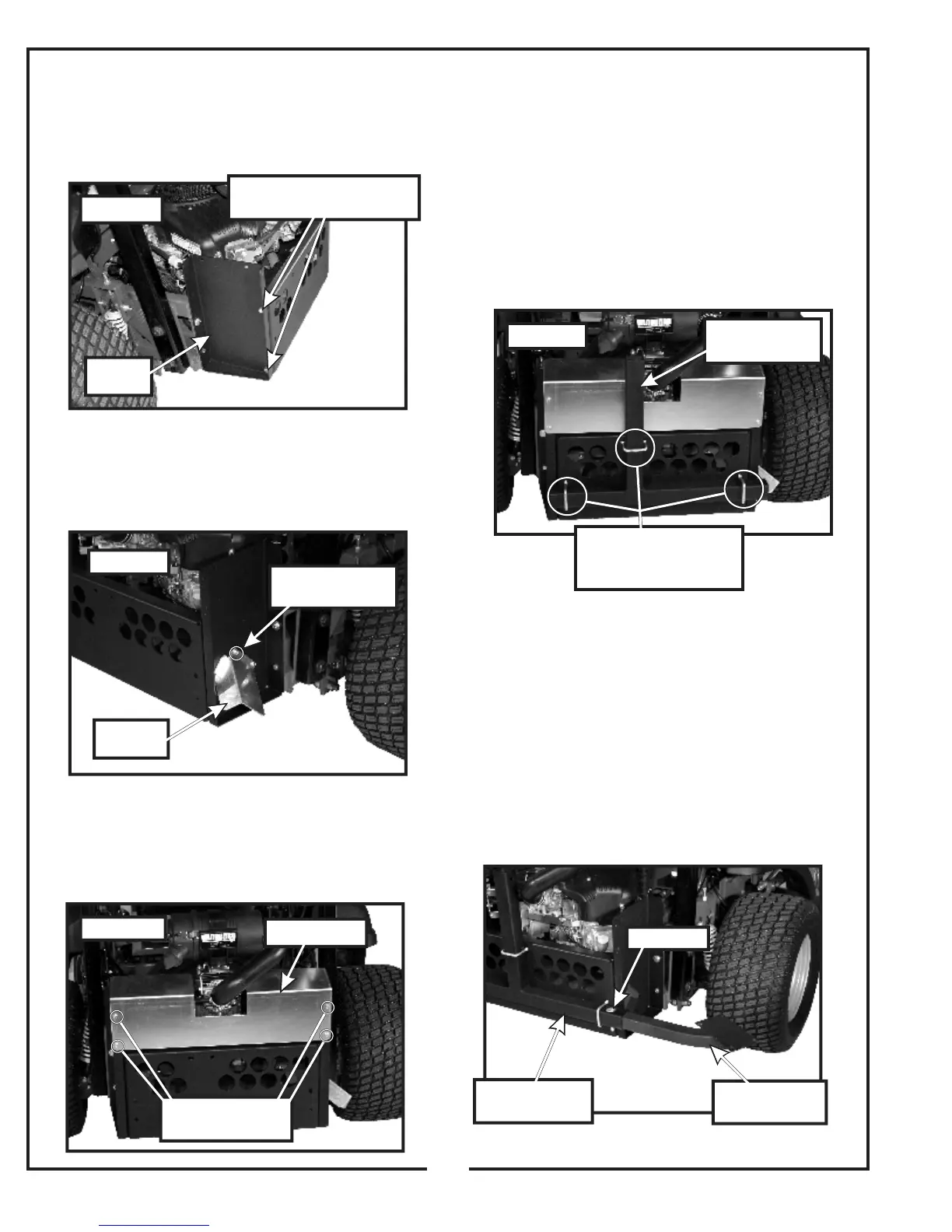
2-3 Lower Stiffener Installation
Attach the lower stiffener P#(B0611) to the left and right
lower main frame legs, using (4) 3/8”-16 x 1-1/4” HHCS
P#(K1192) and (4) 3/8”-16 nyloc nuts P#(K1216). Refer
to Figure 2-3.
2-4 Exhaust Deflector Installation
Fasten the exhaust deflector P#(C0062) to the right
lower main frame leg using (3) 1/4”-20 x ½” HWHTCS
P#(K0353). Refer to Figure 2-4.
2-5 Debris Shield Installation
Fasten the debris shield P#(C0063) to the left and right
lower main frame legs, using (4) 1/4”-20 x ½” HWHTCS
P#(K0353). Refer to Figure 2-5.
2-6 Lower Mount Tube Assembly
Installation
Fasten the lower mount tube assembly P#(A1400) to the
lower stiffener using (3) 3/8”-16 x 2-1/4” u-bolts
P#(K1119), (3) 3/8” flat washers P#(K0047), and (6) 3/8”-
16 nyloc nuts P#(K1216). Use the flat washers on the
slotted mounting holes located on the lower stiffener.
Position the engine mount arm assembly mount hole to
the right side of the mower. Refer to Figure 2-6.
2-7 Engine Mount Arm Assembly
Installation
Position the engine mount arm assembly P#(A0138) as
shown in Figure 2-7. Insert the engine mount arm
assembly into the lower mount tube assembly, and align
the mounting holes on both parts. Secure the engine
mount arm assembly, using (1) detent pin P#(J0248).
Refer to Figure 2-7.
6
(3) 1/4”-20 x 1/2”
HWHTCS
Exhaust
Deflector
Figure 2-7
Lower
Stiffener
(4) 3/8”-16 x 1-1/4” HHCS
(4) 3/8”-16 Nyloc Nut
Figure 2-3
Figure 2-5
(4) 1/4”-20 x 1/2”
HWHTCS
Debris Shield
Figure2-6
(3) 3/8”-16 U-Bolt
(3) 3/8” Flat Washer
(6) 3/8”-16 Nyloc Nut
Lower Mount
Tube Assembly
Figure 2-7
Engine Mount
Arm Assembly
Lower Mount
Tube Assembly
Detent Pin