42 ferrismowers.com
1. Park the unit on a flat, level surface such as a concrete
floor. Disengage the PTO, engage the parking brake, turn
the ignition switch to OFF, and remove the ignition key.
Verify the tires are inflated to the correct pressure.
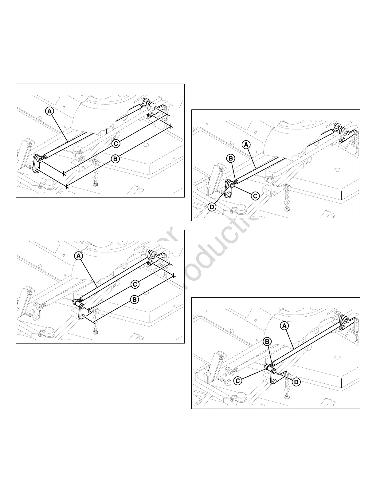
2. To check the inner lift rod (A, Figure 63) timing, measure
and record the distance between the inner lift pivots (B)
and the inner rod pivots (C). Repeat for other side of unit.
63
3. To check the outer lift rod (A, Figure 64) timing, measure
and record the distance between the outer lift pivots (B)
and the outer rod pivots (C). Repeat for other side of unit.
64
4. If the measurements for the inner rods are equal, and
the measurements for the outer rods are equal, no
further adjustment is required. If the measurements are
NOT equal (greater than 1/8” (3,17 mm) difference),
adjustment is required, continue with Adjusting the Deck
Lift Rod Timing.
Adjusting the Deck Lift Rod Timing
1. Fully depress the deck lift pedal to lock the cut height
in the 6" (15,2 cm) position. Remove the cutting height
adjustment pin and lower the mower deck.
2. To ensure that the deck is in the lowest position, push the
pedal by hand towards the rear of the unit and install the
height adjustment pin in the 3” (7.6 cm) position to hold in
place.
3. Block up the mower deck until all deck lift linkages are
slack.
4. To adjust the inner lift rod (A, Figure 65): Loosen the
jam nut (B) on the front ball joint (C) then remove the
1/2” hardware (D) fastening the ball joint to the lift pivot
arm. Turn the ball joint clockwise to shorten the distance
between the rod pivots or counter-clockwise to lengthen
the distance between the rod pivots. Install the ball joint
on the lift pivot arm and secure with the 1/2” hardware
previously removed. Tighten the jam nut against the lift
rod.
65
5. To adjust the outer lift rod (A, Figure 66): Loosen the
jam nut (B) on the front ball joint (C) then remove the
1/2” hardware (D) fastening the ball joint to the lift pivot
arm. Turn the ball joint clockwise to shorten the distance
between the rod pivots or counter-clockwise to lengthen
the distance between the rod pivots. Install the ball joint
on the lift pivot arm and secure with the 1/2” hardware
previously removed. Tighten the jam nut against the lift
rod.
66
6. Remove blocks from under the mower deck.
7. Remove the cutting height adjustment pin from in front
of the deck lift pedal arm. Lift mower deck and install the
cutting height adjustment pin in the desired cutting height.
 Loading...