INSTALLATION OF THE UNIT
Choice of the installation site. In compliance with the con-
ditions, position the unit as low as possible, but always ensu-
re that there is 10 cm free space above it. Before fixing the
unit to the wall, make sure that this latter is able to bear the
weight of the machine, that the air flow is not obstructed by
curtains or other, and that the position is able to guarantee
that the ais apreads in an optimal way around the room.
Installation. Once the position of the interior unit has been
chosen, use the fixing plate (Fig.1) as a template so as to
identify the exact positions of the expansion plugs and the
hole that passes through the wall.
MACHINE INSTALLATION
Models 30-V / 40-V
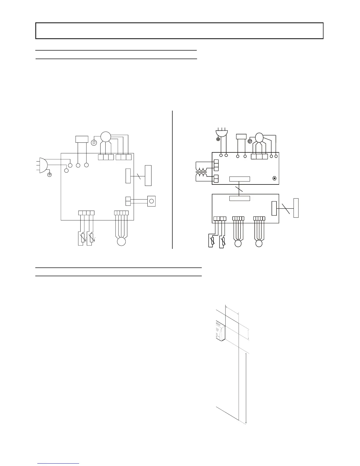
WIRING DIAGRAMS
To allow the conditioner to operate, the electrical connections must be made as indicated on the wiring diagrams sup-
plied with the machine. It is essential for the units to be connected to an efficient ground ground system. The
manufacturer declines all liability for failure to comply with this precaution.
NOTE: Refer to the wiring diagrams supplied with the machine for all work involving the electrical system.
Model 20-V
8
 Loading...