EasyManuals Logo

Ferroli divaproject C24 User Manual

Ferroli divaproject C24
To Next Page IconTo Next Page
To Previous Page IconTo Previous Page
Page #11 background imageLoading...
Page #11 background image
DIVAPROJECT C24
11
IT
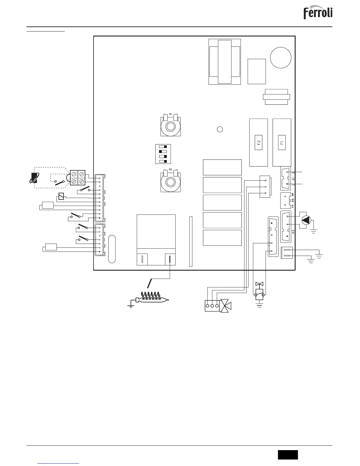
5.6 Schema elettrico
fig. 15 - Schema elettrico
A
Attenzione: Prima di collegare il termostato ambiente o il cronocomando remoto, togliere il ponticello sulla morsettiera.
32 Circolatore riscaldamento
34 Sensore riscaldamento
38 Flussostato
42 Sensore temperatura sanitario
44 Valvola gas
47 Modureg
49 Termostato di sicurezza
72 Termostato ambiente (opzionale)
81 Elettrodo d’accensione/rivelazione
95 Valvola deviatrice
114 Pressostato acqua
126 Termostato fumi
139 Cronocomando remoto (opzionale)
X4
1
2
3
4
5
6
7
114
42
47
38
72
T.
L
N
230V
50 Hz
1
3
2
32
X7
1
44
81
1
2
3
4
5
6
7
8
9
10
11
X2
DBM33B
PT1
PT2
49
126
34
T.
1234
ON DIP
3.15A 250Vac
2
3
4
95
1 2 3
139
FRG*5HY

Questions and Answers:

Question and Answer IconNeed help?

Do you have a question about the Ferroli divaproject C24 and is the answer not in the manual?

Ferroli divaproject C24 Specifications

General IconGeneral
BrandFerroli
Modeldivaproject C24
CategoryBoiler
LanguageEnglish

Related product manuals