DIVAPROJECT C24
42
EN
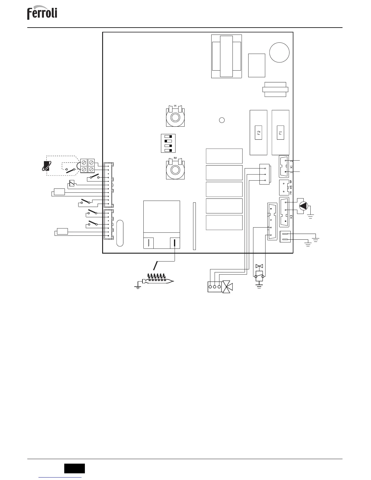
fig. 15 - Wiring diagram
A
Attention: Remove the jumper on the terminal block before connecting the room thermostat or remote timer control.
32 Heating circulating pump
34 Heating sensor
38 Flow switch
42 DHW temperature sensor
44 Gas valve
47 Modureg
49 Safety thermostat
72 Room thermostat (optional)
81 Ignition/detection electrode
95 Diverter valve
114 Water pressure switch
126 Fume thermostat
139 Remote timer control (optional)