DIVAPROJECT F24
26
EN
cod. 3541F161 - Rev. 00 - 05/2014
Table. 5 - Typology
For connection of the separate ducts, fit the unit with the following starting accessory:
fig. 8 - Starting accessory for separate ducts
Before proceeding with installation, check the baffle to be used and make sure the max-
imum permissible length has not been exceeded, by means of a simple calculation:
1. Completely establish the layout of the system of split flues, including accessories
and outlet terminals.
2. Consult the table 7 and identify the losses in m
eq
(equivalent metres) of every com-
ponent, according to the installation position.
3. Check that the sum total of losses is less than or equal to the maximum permissible
length in table 6.
Table. 6 - Baffles for separate ducts
Table. 7 - Accessories
Connection to collective flues
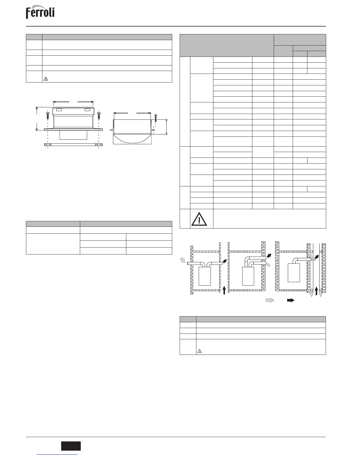
fig. 9 - Examples of connection to flues ( = Air / = Fumes)
Table. 8 - Typology
If the boiler is to be connected DIVAPROJECT F24 to a collective flue or a single flue
with natural draught, the flue or chimney must be expressly designed by professionally
qualified technical personnel in conformity with the current regulations and be suitable
for sealed chamber units equipped with fan.
Type Description
C1X
Wall horizontal exhaust and intake. The inlet/outlet terminals must be concentric or close enough to be
undergo similar wind conditions (within 50 cm)
C3X
Roof vertical exhaust and intake. Inlet/outlet terminals like for C12
C5X
Wall or roof exhaust and intake separate or in any case in areas with different pressures. The exhaust
and intake must not be positioned on opposite walls.
C6X
Intake and exhaust with separately certified pipes (EN 1856/1)
B2X
Intake from installation room and wall or roof exhaust
IMPORTANT - THE ROOM MUST BE PROVIDED WITH APPROPRIATE VENTILATION
Separate ducts
Max. permissible length
60 m
eq
Baffle to use
0 - 20 m
eq
Ø 43
20 - 45 m
eq
Ø 47
45 - 60 m
eq
No baffle
Losses in m
eq
Air
inlet
Fume exhaust
Vertical Horizontal
Ø 80
PIPE
0.5 m M/F 1KWMA38A 0.5 0.5 1.0
1 m M/F 1KWMA83A 1.0 1.0 2.0
2 m M/F 1KWMA06K 2.0 2.0 4.0
BEND
45° F/F 1KWMA01K 1.9 2.9
45° M/F 1KWMA65A 1.9 2.9
90° F/F 1KWMA02K 2.0 3.0
90° M/F 1KWMA82A 1.5 2.5
90° M/F + Test point 1KWMA70U 1.5 2.5
PIPE SECTION
with test point 1KWMA16U 0.2 0.2
for condensate drain 1KWMA55U - 3.0
TEE
for condensate drain 1KWMA05K - 7.0
TERMINAL
air, wall 1KWMA85A 2.0 -
fumes, wall with antiwind 1KWMA86A - 5.0
FLUE
Split air/fumes 80/80 1KWMA84U - 12.0
Fume outlet only Ø80 1KWMA83U +
1KWMA86U
-4.0
Ø 100
REDUCTION
from Ø80 to Ø100 1KWMA03U 0.0 0.0
from Ø100 to Ø80 1.5 3.0
PIPE
1 m M/F 1KWMA08K 0.4 0.4 0.8
BEND
45° M/F 1KWMA03K 0.6 1.0
90° M/F 1KWMA04K 0.8 1.3
TERMINAL
air, wall 1KWMA14K 1.5 -
fumes, wall with antiwind 1KWMA29K - 3.0
Ø 60
PIPE 1 m M/F 010028X0 - 2.0 6.0
BEND 90° M/F 010029X0 - 6.0
REDUCTION 80 - 60 010030X0 - 8.0
TERMINAL fumes, wall 1KWMA90A - 7.0
ATTENTION: CONSIDER THE HIGH PRESSURE LOSSES OF Ø60 ACCESSORIES;
USE THEM ONLY IF NECESSARY AND AT THE LAST FUME EXHAUST SECTION.
Type Description
C2X
Intake and exhaust in common flue (intake and exhaust in same flue)
C4X
Intake and exhaust in common and separate flues , but undergoing similar wind conditions
C8X
Exhaust in single or common flue and wall intake
B3X
Intake from installation room by means of concentric duct (that encloses the exhaust) and exhaust in
common flue with natural draught
IMPORTANT - THE ROOM MUST BE PROVIDED WITH APPROPRIATE VENTILATION
 Loading...