EasyManuals Logo

Ferroli DIVAPROJECT F24 User Manual

Ferroli DIVAPROJECT F24
To Next Page IconTo Next Page
To Previous Page IconTo Previous Page
Page #32 background imageLoading...
Page #32 background image
DIVAPROJECT F24
32
EN
cod. 3541F161 - Rev. 00 - 05/2014
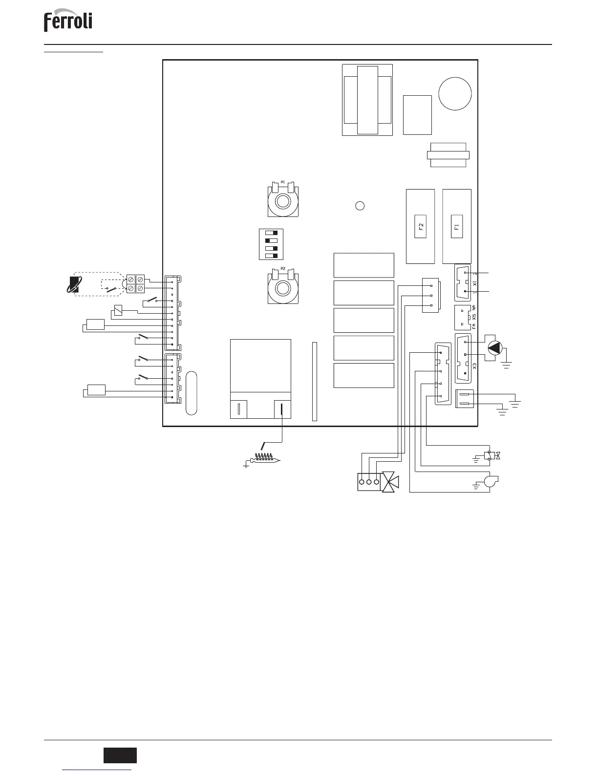
5.6 Wiring diagram
fig. 21 - Wiring diagram
A
Attention: Remove the jumper on the terminal block before connecting the room thermostat or the remote timercontrol.
16 Fan
32 Heating circulating pump
34 Heating sensor
38 Flow switch
42 DHW temperature sensor
43 Air pressure switch
44 Gas valve
47 Modureg
49 Safety thermostat
72 Room thermostat (optional)
81 Ignition/detection electrode
95 Diverter valve
114 Water pressure switch
139 Remote timer control (optional)
X4
1
2
3
4
5
6
7
114
42
47
38
72
T.
L
N
230V
50 Hz
1
3
2
32
X7
1
44
16
81
1
2
3
4
5
6
7
8
9
10
11
X2
DBM33B
PT1
PT2
49
43
34
T.
1234
ON DIP
PR08202
3.15A 250Vac
2
3
4
95
1 2 3
139

Questions and Answers:

Question and Answer IconNeed help?

Do you have a question about the Ferroli DIVAPROJECT F24 and is the answer not in the manual?

Ferroli DIVAPROJECT F24 Specifications

General IconGeneral
BrandFerroli
ModelDIVAPROJECT F24
CategoryBoiler
LanguageEnglish

Related product manuals