ECONCEPT TECH 25 C
30 EN
cod. 3540I371 - 06/2008 (Rev. 00)
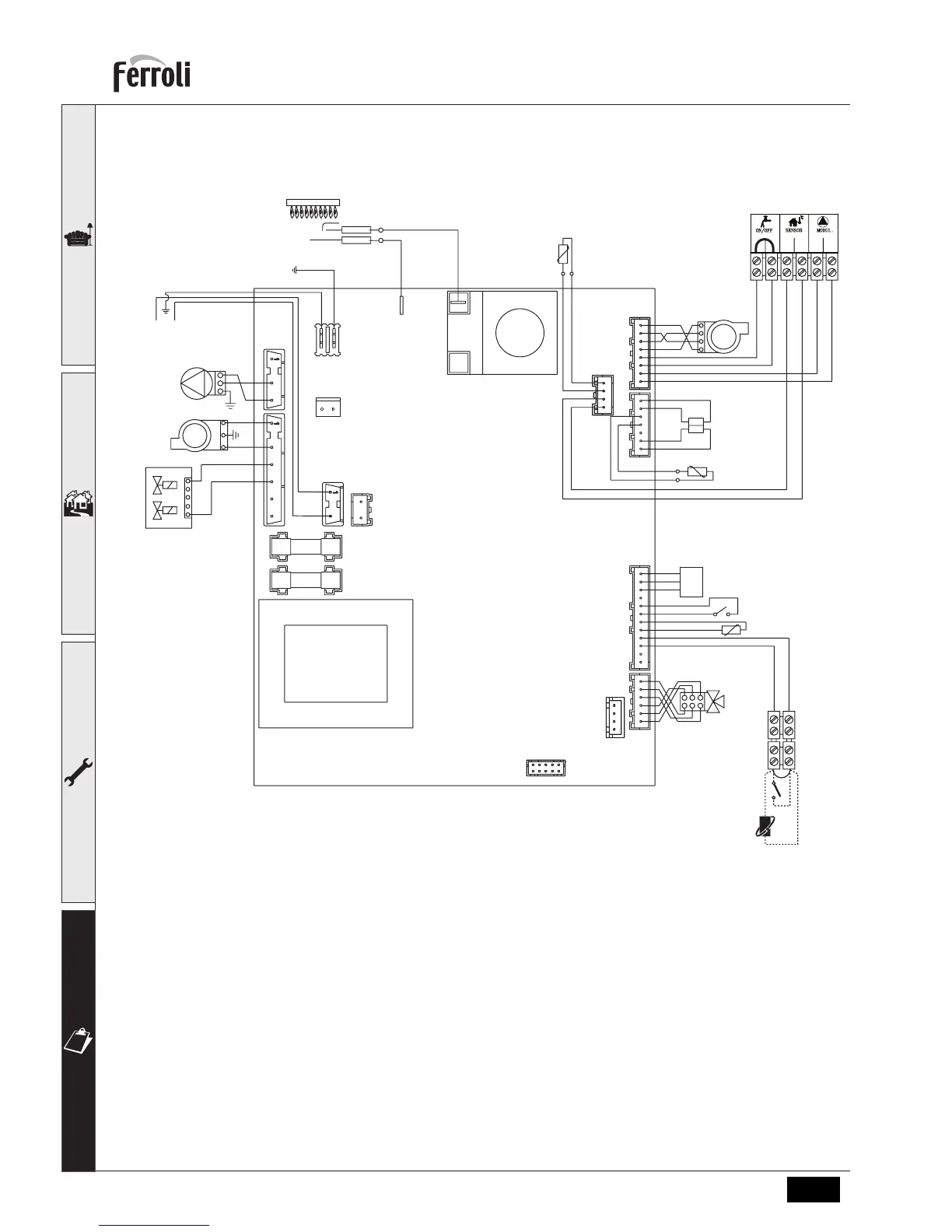
4.6 Wiring diagram
fig. 33 - Wiring diagram
A
Caution: Before connecting the room thermostat or the remote timer control, remove the jumper on the
terminal block.
16 Fan
32 Heating circulator
42 Tap water temperature sensor
44 Gas valve
72 Room thermostat
82 Detection electrode
95 Diverter valve
114 Water pressure switch
136 Flow meter
138 External sensor
139 Remote timer control
186 Return sensor
188 Ignition electrode
191 Fume temperature sensor
278 Double sensor (heating + safety)
A Flow meter ON/OFF contact
72
95
42
114
136
191
16
186
188
82
T° T°
278
139
138A
32
16
44
NL
230V
50Hz
GND
OUT
+5V
123456
DBM04A
 Loading...