Ferroli F24
18
For further accessories please refer to:
"Flue system manual for room sealed
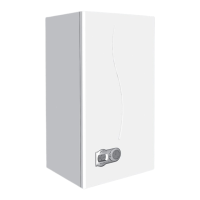
boiler"Example of calculation for wall
inlet/outlet with 2 pipe system
maximum total fl ue length: 48 metres
Attention: Resistance of flue restrictor (if req.)
is included (see table on page 13)
Remove the flue restrictor.
The flue and air pipes must have an inclination
downward equal to 3% from boiler to outside.
Fig. 20
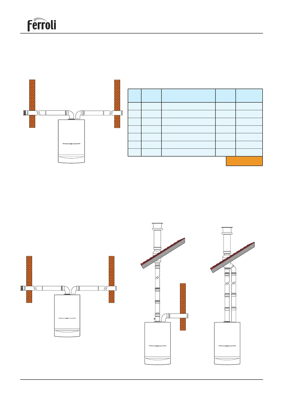
Example of wall inlet/outlet
2 pipe application
Example of roof
inlet/outlet
Example of direct roof fl ue outlet
and wall air inlet
3.04.4 Example of other installation with two pipe systems
Fig. 21
Fig. 23Fig. 22
Ref.
N° of
pieces
Description Code
Length or
reduction
1
2
3
4
5
6
7
1
13
1
1
1
12
1
Air bend 80 mm R/D = 0,75 1,5 m
Horizontal air pipe 13,0 m
Air wall terminal 2,0 m
Air inlet closing flange —
Flue bend 80 mm R/D = 0,75 2,5 m
Horizontal flue 24,0 m
Air wall terminal outlet flue 5,0 m
Total 48,0 m
 Loading...