Ferroli F24
43
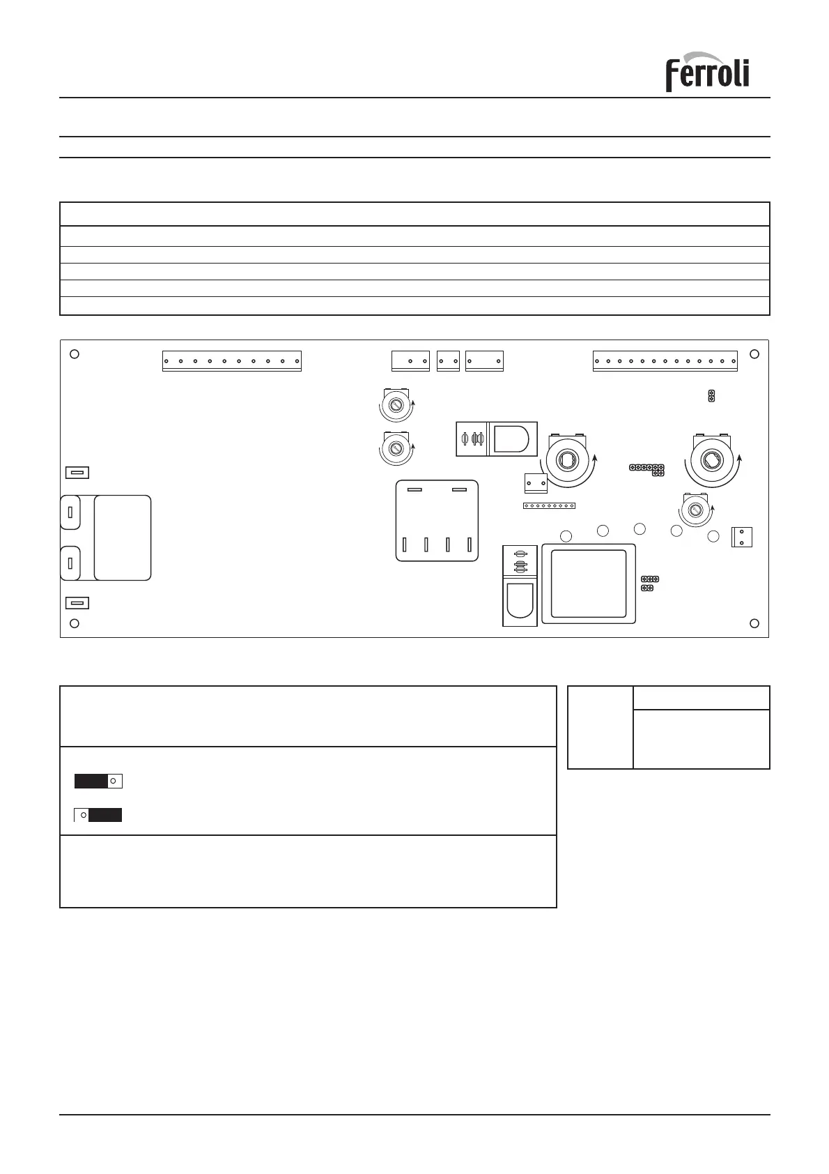
JP01 ON =
Delay between shutdown and re-ignition disabled
JP01 OFF =
Delay between shutdown and re-ignition enabled
JP02:
Jumper on for natural gas
Jumper on for LPG
JP03 ON = Max temperature D.H.W. 62°C
JP03 OFF= Max temperature D.H.W. 55°C (standard)
Potentiometer adjustment
P1 = Central heating flow temperature adjustment
P2 = Domestic hot water temperature adjustment
P3 = Central heating flow output adjustment
P4 = Ignition gas pressure adjustment
P5 = Minimum gas pressure adjustment
9. ELECTRICAL AND FUNCTIONAL SCHEME
9.01 Main components layout on electronic boards
temp. Ohm
10 °C 20 kOhm
25 °C 10 kOhm
60 °C 2,5 kOhm
80 °C 1,25 kOhm
Temp.
sensor
NTC
(34) (42)
Fig. 41
X6
X1 X2 X3 X4
12121312345678910 123
45
678910
111213
21
X5
L1
L2
L3
L4
L5
+- +-
Transformer
P2
DHW
X12
12
+
-
P3
+
-
P5
+
-
P4
JP02
JP01
JP03
123456789
X10
Nat/LPG
P1
CH
X11
RY100
RY101
PC PNO L N HL HL MV1 MV2 MV3 MV4
FAN
LN
X8
X7
MF03F