22
INSTALLATION
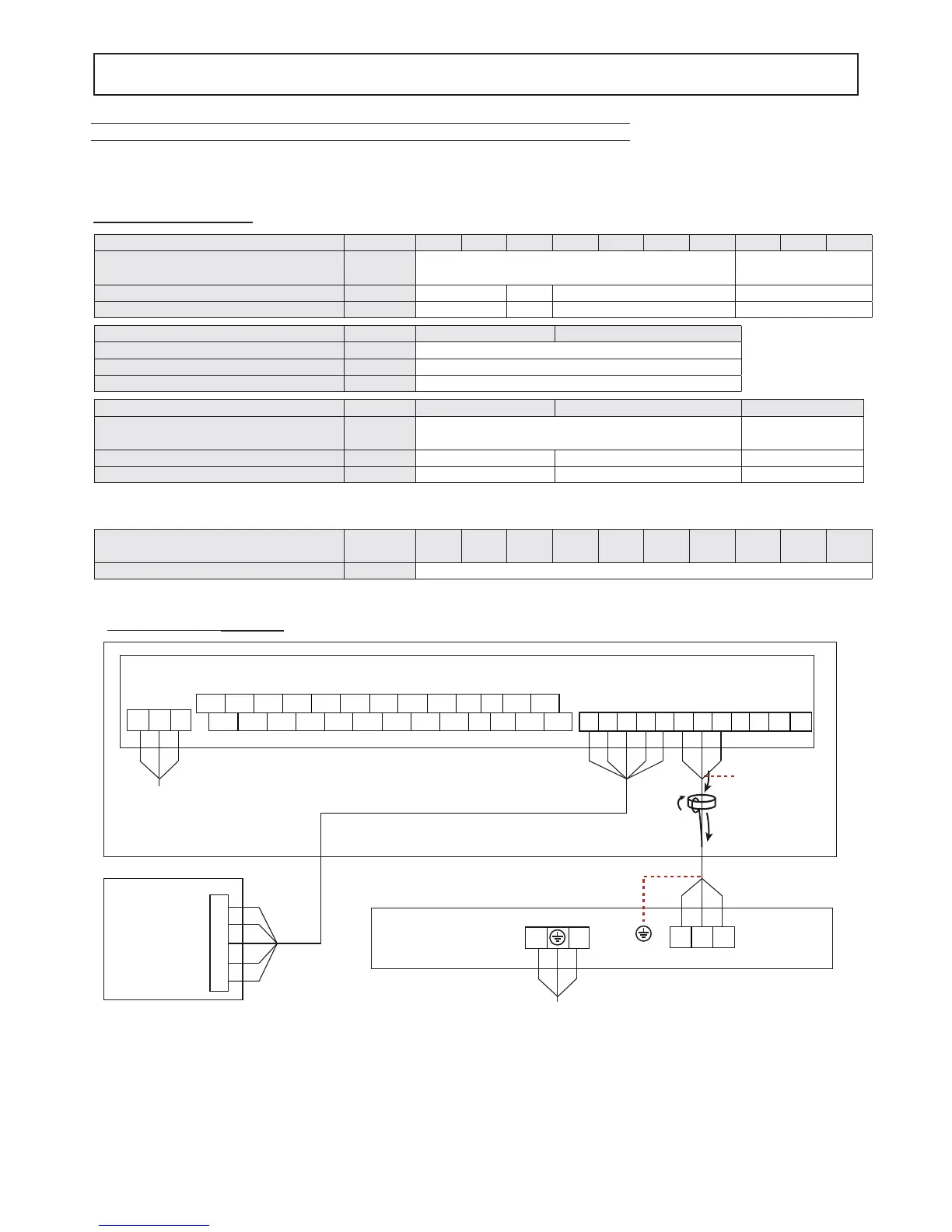
Power supply connection
Electrical connections
Procedure
1. Connect the cables to the appropriate terminals as shown on the diagram.
2. Fix the cables with cable ties.
Recommended cable H05RN-F or as installed. See specifi c legislation. The customer must install the automatic circuit
breaker.
Outdoor unit MOD.
4 6 8 10 12 14 16 12T 14T 16T
Power input " 220-240V 50 Hz
380-415V 3+N+PE
50Hz
Automatic circuit breaker A 16 20 32 16
Power supply cross-section of cable mm
2
3x2,5 3x4,0 3x4,0 5x2,5
Cavo di comunicazione
tra unità interna ed esterna
MOD.
4 6 8 10 12 14 16 12T 14T 16T
Wiring size (shielded cable)
mm
2
3x0,75
Indoor unit without booster MOD.
816
Power input " 220-240V 50 Hz
Automatic circuit breaker A 2
Power supply cross-section of cable mm
2
3x1,0
Indoor unit with booster MOD.
81616T
Power input " 220-240V 50 Hz
380-415V 3+N+PE
50Hz
Automatic circuit breaker A 16 16 10
Power supply cross-section of cable mm
2
3x2,5 3x2,5 5x2,5
Indoor Unit
Outdoor Unit
Power Supply
3-shield wire
COMANDO
REMOTO
ABXYE
ABXYE
P Q E T5 T5 T1b T1b
IBH1 IBH2 PE TH N C H A1 A2 N N N PE
IBH1 IBH2
LPE
PE
N
TH PE TBH L1
AHS1 AHS2
P_o PEPE P_d SV2
Power Supply
LN
EQP
Mod. 4 - 6 - 8 - 10 - 12 - 14 - 16
NOTA
Connect the communication cable between indoor unit and outdoor unit keeping the correspondence of the letters
indicated on the terminals (P with P, Q with Q, E with E).
Connect the communication cable between indoor unit and remote control keeping the correspondence of the let-
ters indicated on the terminals (A with A, B with B....).
OUTDOOR UNIT
REMOTE
CONTROL
power supplie
power supplie
comunication
(shielded cable)
INDOOR UNIT
☞
fi g. 1
 Loading...