12
INSTALLATION
Select an installation site where the following conditions are satisfi ed and one that meets with your customer's approval.
• Places that are well-ventilated.
• Places where the unit does not disturb next-door neighbors.
• Safe places which can bear the unit's weight and vibration and where the unit can be installed at an even level.
• Places where there is no possibility of fl ammable gas or product leak.
• The equipment is not intended for use in a potentially explosive atmosphere.
• Places where servicing space can be well ensured.
• Places where the units' piping and wiring lengths come within the allowable ranges.
• Places where water leaking from the unit cannot cause damage to the location (e.g. in case of a blocked drain pipe).
• Places where rain can be avoided as much as possible.
• Do not install the unit in places often used as a work space. In case of construction work (e.g. grinding etc.) where a lot of dust
is created, the unit must be covered.
• Do not place any objects or equipment on top of the unit (top plate)
• Do not climb, sit or stand on top of the unit.
• Be sure that suffi cient precautions are taken in case of refrigerant leakage according to relevant local laws and regulations.
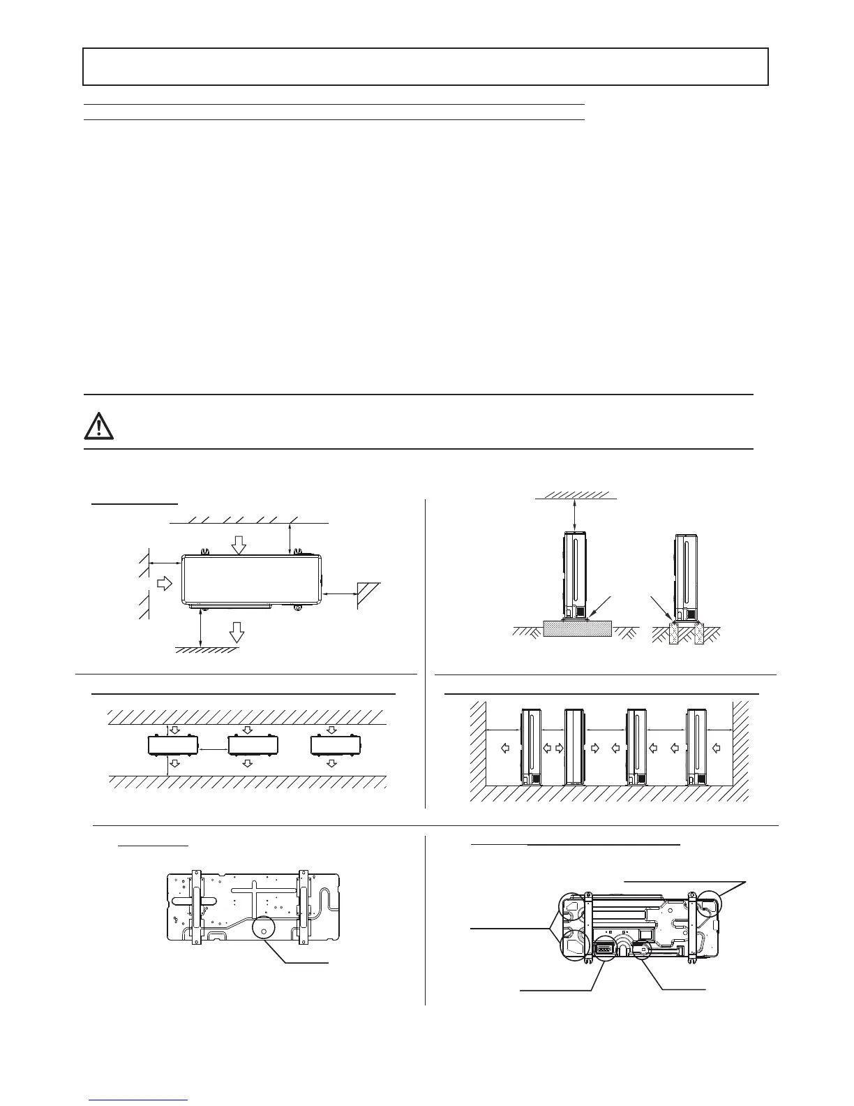
Selecting the installation site and minimum operating area outdoor unit
Be sure to provide for adequate measures in order to prevent that the unit be used as a shelter by small animals. Small animals making
contact with electrical parts can cause malfunctions, smoke or fi re. Please instruct the customer to keep the area around the unit clean.
WARNING
>300
>300
>2000
>600
(Wall or obstacle)
Maintain
channel
Air outlet
Air inlet
ir inlet
air outlet
air inlet
wall / obstacle
Single installation
air inlet
Multiple installation in parallel between 2 or more units (front / back)
>2000 >500 >3000 >3000 >300
Multiple installation in parallel between 2 or more units (lateral)
>600
>2000
>300
Water Outlet
condensation drain
Mod. 4 - 6 - 8
Fix with bolt
>600mm
fasten with
bolts
fi g. 1
fi g. 2
fi g. 3
fi g. 4
fi g. 5
fi g. 6
Reserve water outlet
Reserve water outlet Water Outlet
(Need to knock open)
condensation drain
condensation drain reserve
(rubber stopper)
(semi-sheared)
(semi-sheared)
condensation drain reserve
input of power cables and refrigerant pipes
Mod. 10 - 12 - 12T - 14 - 14T - 16 - 16T
 Loading...